
User manual


OLIMEX© 2013 STM32-E407 user's manual
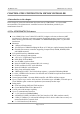
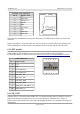
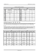
PF PG
Pin # Signal name Pin # Signal name Pin # Signal name Pin # Signal name
1 +3.3V 11 PF8/A3* 1 +3.3V 11 PG8/D7*
2 GND 12 PF9/A4* 2 GND 12 PG9
3 PF0 13 PF10/A5* 3 PG0 13 PG10/UEXT_CS
4 PF1 14 PF11/A6* 4 PG1 14 PG11/TX_EN
5 PF2 15 PF12 5 PG2 15 PG12/D8*
6 PF3 16 PF13 6 PG3 16 PG13/TXD0
7 PF4 17 PF14 7 PG4 17 PG14/TXD1
8 PF5 18 PF15 8 PG5 18 PG15/D9*
9 PF6/A1* 19 +5V 9 PG6 19 +5V
10 PF7/A2* 20 GND 10 PG7/D6* 20 GND
Note that all signals marked with asterisk (*) are multiplexed with signals of the Arduino platform.
Those signals can be controlled by the provided jumpers. However, the jumpers are soldered by
default which enables them on the GPIO connector and the Arduino shield at the same time.
PG11, PG13, PG14, PG16 and PG17 are multiplexed with the UEXT and the Ethernet. Their
connection is not controlled by jumpers.
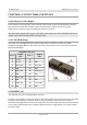
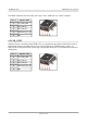
6.9 PWR Jack
The power jack used is the typical 2.5mm one used by Olimex in most of our products. You should
provide between 6 and 16 volts @ 1A to the board.
Pin # Signal name
1 Power input
2 GND
More info about the power supply can be found in chapters 2 and 5 of this manual.
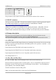
6.10 Battery connector
When using the battery connector keep in mind that it is an energy solution that wouldn't be able to
power the board and all the peripherals!
It help keeping information in the processor if you need to transport the board from one power
supply to other.
Page 19 of 30