
User manual


OLIMEX© 2013 STM32-E407 user's manual
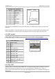
Pin # Signal name
1 VBAT
2 GND
The pin names are also written on the bottom of the board in the base of the connector.
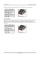
6.11 BOOT connector
The best use for the GND, RX3, TX3 pins from the BOOT connector would be getting the output of
the available demo program on a computer terminal via USB-SERIAL-CABLE-F
(https://www.olimex.com/dev/usb-serial-cable.html)
U3BOOT are 3 pinholes set on USART3 and are named on the bottom – GND, RX3, TX3 and
notice there are two vias near them which are actually VCC and can be used if connecting
U3BOOT. More information about booting over UART can be found in the processor's datasheet.
6.12 Jumper description
Please note some of the jumpers on the board are SMD type. If you feel insecure in your
soldering/cutting technique it is better not to try adjusting SMD jumpers.
Also if you feel incapable of removing the PTH jumper with hand better use tweezers. We do.
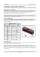
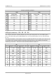
6.12.1 PWR_SEL
PWR_SEL is important PTH jumper allowing easy switching of input current. You can use tweezers
to reach it. If you are powering the board via the PWR_JACK set it to position 1-2 (default → to the
near edge of the board).
If powering from the JTAG/SWD set the jumper in position 3-4.
If powering from the USB-OTG2 set it in 5-6 position (near battery connector).
If powering from the USB-OTG1 set it in 7-8 position (near LAN connector).
The default position is 1-2.
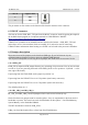
6.12.2 B1_1/B1_0 and B0_1/B0_0
B1_1/B1_0 and B0_1/B0_0 are PTH jumpers which can be moved relatively easy.
Notice that these two jumpers must be moved together – they are responsible for the boot mode if
bootloader is present. The board can search for bootloader on three places – User Flash Memory,
System Memory or the Embedded SRAM.
The DFU bootloader is found on USB_OTG1.
If B0_0 is closed the board will try to boot from User Flash Memory.
Page 20 of 30