
User manual
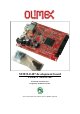


OLIMEX© 2013 STM32-E407 user's manual
6.11 BOOT connector .................................................................................................................. 20
6.12 Jumper description .............................................................................................................. 20
6.12.1 PWR_SEL ................................................................................................................................................... 20
6.12.2 B1_1/B1_0 and B0_1/B0_0 ......................................................................................................................... 20
6.12.3 R-T ............................................................................................................................................................... 21
6.12.4 3.3V_E ......................................................................................................................................................... 21
6.12.5 AGND_E ...................................................................................................................................................... 21
6.12.6 AREF_EN .................................................................................................................................................... 21
6.12.7 GPIO port jumpers .................................................................................................................................... 21
6.13 Additional hardware components ...................................................................................... 21
CHAPTER 7 BLOCK DIAGRAM AND MEMORY ............................................. 23
7. Introduction to the chapter ..................................................................................................... 23
7.1 Processor family block diagram ........................................................................................... 23
7.2 Physical memory map ........................................................................................................... 24
CHAPTER 8 SCHEMATICS ................................................................................... 25
8. Introduction to the chapter ..................................................................................................... 25
8.1 Eagle schematic ...................................................................................................................... 25
8.2 Physical dimensions ............................................................................................................... 27
CHAPTER 9 REVISION HISTORY AND SUPPORT .......................................... 28
9. Introduction to the chapter ..................................................................................................... 28
9.1 Document revision ................................................................................................................. 28
9.2 Board's revision ...................................................................................................................... 28
9.3 Useful web links and purchase codes ................................................................. 29
9.4 Product support ..................................................................................................................... 30
Page 4 of 30