STM-H103 development board user's manual Rev.
INTRODUCTION: STM32-H103 board is an entry level development board for the new ARM Cortex M3 family of devices produced by ST Microelectronics Inc. With STM32-H103 you can explore the features of STM32 family on budged, the board have everything necessary to build simple applications: USB port where power is taken and power supply circuit, reset and oscillator circuits, JTAG port for programming and debugging, two status LEDs and user button.
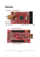
BOARD LAYOUT: Page 3 of 18
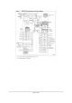
SCHEMATIC: Please note that the schematic suits two boards STM32-H103 and SMT32-H405. There is a slight variation mentioned over the microcontroller.
PROCESSOR FEATURES: STM-H103 board use ARM 32-bit Cortex™-M3 CPU STM32F103RBT6 from ST Microelectronics with these features: - CPU clock up to 72Mhz - FLASH 128KB - RAM 20KB - DMA x7 channels - RTC - WDT - Timers x3+1 - SPI x2 - I2C x2 - USART x3 - USB x1 - CAN x1 (multiplexed with USB so both can't be used in same time) - GPIO up to 51 (multiplexed with peripherials) - 2 ADC 12-bit - operating voltage 2.0-3.
Page 6 of 18
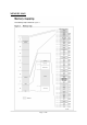
MEMORY MAP: Page 7 of 18
POWER SUPPLY CIRCUIT: STM32-H103 can take power from two sources: - USB connector where 5V power supply is applied by USB host - Vin input in extension pin EXT2.26 where +5-9V may be applied The board power consumption is: about 40 mA with all peripherials and MCU running at full speed, there are different power saving modes which may put STM32F103RBT6 in power sleep mode and in these modes the consumption of the MCU is only few micro ampers.
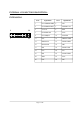
EXTERNAL CONNECTOR DESCRIPTION: EXTENSION 1 Pin # 2 1 26 25 Signal Name Pin # Signal Name 1 PA11/USBDM/CANRX 2 PA8 3 PA12/USBDP/CANTX 4 PA9/UART1.TX 5 +3.3V out 6 GND 7 PA10/UART1.RX 8 PC10 9 PC11/USBpull 10 PC12/LED 11 PD2 12 PB5/I2C1.SMBA 13 PB6/I2C.SCL 14 PA6/SPI1.MISO 15 PB7/I2C.SDA 16 PB8 17 PB9 18 PA5/SPI1.SCK 19 PC0 20 PC1 21 PB0 22 PA7/SPI1.
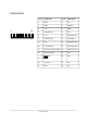
EXTENSION 2 2 1 26 25 Pin # Signal Name Pin # Signal Name 1 VDDA 2 PC2 3 GNDA 4 PA0/BUT 5 3.3V 6 GND 7 PA2/UART2.TX 8 PA1 9 PC3 10 PA3/UART2.RX 11 PA4/SPI1.NSS 12 PC4/USB-P 13 PC5 14 PB10/UART3.TX 15 P11/UART3.RX 16 PB13/SPI2.SCK 17 PB12/SPI2.NSS/I2C.SMBA 18 PB14/SPI2.MISO 19 PB15/SPI2.
JUMPER DESCRIPTION: R-T connects JTAG TRST signal to STM32F103RBT6 RESET Default state closed (shorted) VBAT connects 3.3V to STM32F103RBT6 Vbat pin.1 Default state closed (shorten), Vbat signal is also available to EXT1-23, so if you want to connect external backup battery to the STM32F103RBT6 this jumper should be opened (unshorted) and the external battery to be connected to EXT1-23 pin. USBP-E connects USB power supply to STM32F103RBT6 pin.
INPUT/OUTPUT: User button with name BUT – connected to STM32F103RBT6 pin.14 PA0.WKUP; Status green LED with name STAT connected to STM32F103RBT6 pin.53 PC12, note that LED-E SMT jumper should be shorted to may LED work properly (it’s shorted by default), if you decide to use PC12 port for other purpose you have to remove the solder short on this jumper which will disconnect the LED from PC12 port; Power supply red LED with name PWR – indicates that 3.
RS232: STM32F103RBT6 have 3 USARTs which are available on the extension headers. One of them can operate up to 4.5 Mbit/s, the other two up to 2.25 Mbit/s. They provide hardware management of the CTS and RTS signals, IrDA SIR ENDEC support, are ISO 7816 compliant and have LIN Master/Slave capability. All USART interfaces can be served by the DMA controller. USART1.Tx – pin.42 PA9 EXT1-4 USART1.Rx – pin.43 PA10 EXT1-7 USART2.Tx – pin.16 PA2 EXT2-7 USART2.Rx – pin.17 PA3 EXT2-10 USART3.Tx – pin.
CAN: The STM32F103RBT6 CAN is compliant with specifications 2.0A and B (active) with a bit rate up to 1 Mbit/s. It can receive and transmit standard frames with 11-bit identifiers as well as extended frames with 29-bit identifiers. It has three transmit mailboxes, two receive FIFOs with 3 stages and 14 scalable filter banks. The CAN and USB share same pins PA11/EXT1-1 and PA12/EXT1-3, so you can’t use both CAN and USB on same time.
MECHANICAL DIMENSIONS: Page 15 of 18
AVAILABLE DEMO SOFTWARE: DEMO1. Blinking LED for EW-ARM 5.11 Blinks the on-board LED. DEMO2. USB mouse for EW-ARM 5.11 Creates USB mouse and when board is connected to PC it starts moving the mouse cursor in circle. DEMO3. Blinking LED for GCC+OpenOCD+Eclipse Blinks the on-board LED.
ORDER CODE: STM32-H103 – assembled and tested (no kit, no soldering required) How to order? You can order to us directly or by any of our distributors. Please visit our web site www.olimex.com for more info. All boards manufactured by Olimex LTD are ROHS compliant Document revision history: REV.A - created February 2008 REV.B - updated March 2014 Remember to check the schematics and the board design files to compare the differences. Document revision history: board rev. A 1.
Disclaimer: © 2014 Olimex Ltd. All rights reserved. Olimex®, logo and combinations thereof, are registered trademarks of Olimex Ltd. Other terms and product names may be trademarks of others. The information in this document is provided in connection with Olimex products. No license, express or implied or otherwise, to any intellectual property right is granted by this document or in connection with the sale of Olimex products.