STM32-H107 development board Users Manual All boards produced by Olimex are ROHS compliant Rev.
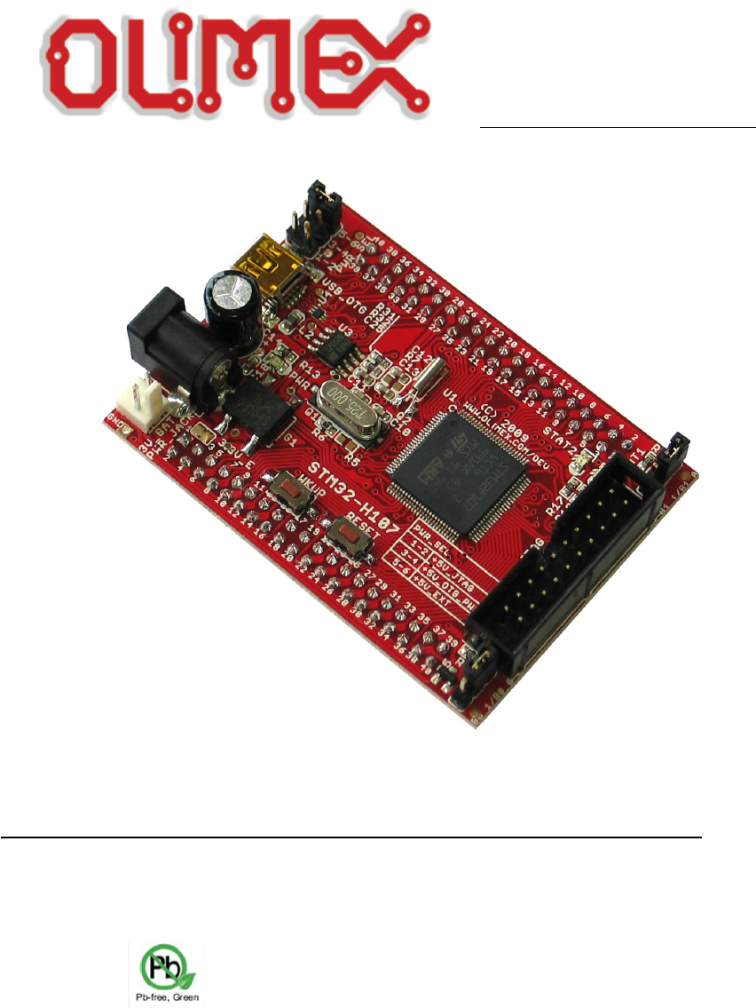
INTRODUCTION STM32-H107 header board provides easy way for developing and prototyping with the new STM32F107VCT6 connectivity line microcontroller, produced by STMicroelectronics. STM32-H107 has JTAG port for programming and debugging, USB_OTG, user button, two status leds, and most of the GPIOs are on extension headers where you can connect your additional circuits.
PROCESSOR FEATURES STM32-H107 board use ARM-based 32-bit microcontroller STM32F107VCT6 with these features: – – – – – Core: ARM 32-bit Cortex™-M3 CPU – 72 MHz maximum frequency, 1.25 DMIPS/MHz (Dhrystone 2.1) performance at 0 wait state memory access – Single-cycle multiplication and hardware division Memories – 256 Kbytes of Flash memory – 64 Kbytes of SRAM Clock, reset and supply management – 2.0 to 3.
– – – four 16-bit timers, each with up to 4 IC/OC/PWM or pulse counter and quadrature (incremental) encoder input – 1 × 16-bit motor control PWM timer with dead-time generation and emergency stop – 2 × watchdog timers (Independent and Window) – SysTick timer: a 24-bit downcounter – 2 × 16-bit basic timers to drive the DAC 14 communication interfaces – 2 × I2C interfaces (SMBus/PMBus) – 5 USARTs (ISO 7816 interface, LIN, IrDA capability, modem control) – 3 SPIs (18 Mbit/s), 2 with a multiple
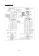
BLOCK DIAGRAM Page5
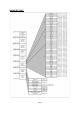
MEMORY MAP Page6
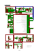
SCHEMATIC 3.3V +5V JTAG +5V_JTAG 10k R27 10k 10k R29 R30 R28 10k TDO RST R-T 2 1 TRST R1 3 2 1 3.3V_MCU_E PB2/BOOT1 100nF C5 100nF C4 100nF C3 100nF C2 100nF C1 10 27 99 74 49 L1 22 C7 100nF + F B0805/600R/200mA(201209-601) C6 10uF/6.3V/TANT 19 VDD VDD VDD VDD VDD R3 C8 100nF C9 NA 21 20 0R(NA) 0R 3.3V 3.3V VSS VSS VSS VSS VSS VDDA 100nF 2.2uF/6.3V VREF+ VREF- 6 R4 HN1x3 0 94 10k VBAT B0_1/B0_0 C10 27pF 12 R5 NA Q1 Q25.
BOARD LAYOUT Page8
POWER SUPPLY CIRCUIT STM32-H107 can take power from three sources: – PWR connector where 9 V DC or 6 V AC is applied by external power source. – +5V_ OTG-PWR from USB OTG – +5V_JTAG from JTAG RESET CIRCUIT STM32-H107 reset circuit includes EXT1 pin 3, EXT2 pin 3, JTAG connector pin 15, STM32F107VCT6 pin 14 (NRST) and RESET button. CLOCK CIRCUIT Quartz crystal 25 MHz is connected to STM32F107 pin 12 (OSC_IN) and pin 13 (OSC_OUT). Quartz crystal 32.
Default state is open. INPUT/OUTPUT Status LED1 (green) with name STAT1 connected to STM32F107VCT6 pin 63 (PC6/I2S2_MCK/TIM3_CH1). Status LED2 (yellow) with name STAT2 connected to STM32F107VCT6 pin 64 (PC7/I2S3_MCK/TIM3_CH2). Power-on LED (red) with name PWR – this led shows that +3.3V is applied to the board. User button with name WKUP connected to STM32F107VCT6 pin 23 (PA0/WKUP). Reset button with name RESET connected to STM32F107VCT6 pin 14 (NRST).
PULL-DOWN 12 GND 13 TDO 14 GND 15 RST 16 GND 17 PULL-DOWN 18 GND 19 +5V_JTAG 20 GND PWR_JACK: Pin # Signal Name 1 Power Input 2 GND USB_OTG Pin # Signal Name 1 +5V_OTG_PWR 2 USB_OTG_D- 3 USB_OTG_D+ 4 OTG_ID 5 GND 3V_BAT Pin # Signal Name 1 VBAT 2 GND Page11
EXT1 Pin # Signal Name Pin # Signal Name 1 3.
EXT2 Pin # Signal Name Pin # Signal Name 1 3.
MECHANICAL DIMENSIONS Page14
AVAILABLE DEMO SOFTWARE – Demo examples Blinking LED and USB OTG for EW-ARM 5.
ORDER CODE STM32-H107 – assembled and tested (no kit, no soldering required) How to order? You can order to us directly or by any of our distributors. Check our web www.olimex.com/dev for more info. Revision history: REV. Initial - create November 2009 REV.A - edited by TU REV. B - more detailed mechanical dimensions added - more programmers added in BOARD USE REQUIREMENTS REV.
Disclaimer: © 2011 Olimex Ltd. All rights reserved. Olimex®, logo and combinations thereof, are registered trademarks of Olimex Ltd. Other terms and product names may be trademarks of others. The information in this document is provided in connection with Olimex products. No license, express or implied or otherwise, to any intellectual property right is granted by this document or in connection with the sale of Olimex products.