STM32-H407 development board USER’S MANUAL Revision D, November 2013 Designed by OLIMEX Ltd, 2012 All boards produced by Olimex LTD are ROHS compliant
OLIMEX© 2013 STM32-H407 user's manual DISCLAIMER © 2013 Olimex Ltd. Olimex®, logo and combinations thereof, are registered trademarks of Olimex Ltd. Other product names may be trademarks of others and the rights belong to their respective owners. The information in this document is provided in connection with Olimex products. No license, express or implied or otherwise, to any intellectual property right is granted by this document or in connection with the sale of Olimex products.
OLIMEX© 2013 STM32-H407 user's manual Table of Contents DISCLAIMER............................................................................................................. 2 CHAPTER 1 OVERVIEW......................................................................................... 5 1. Introduction to the chapter.......................................................................................................5 1.1 Features...........................................................................
OLIMEX© 2013 STM32-H407 user's manual 6.11.1 PWR_SEL............................................................................................... 19 6.11.2 B1_1/B1_0 and B0_1/B0_0.....................................................................19 6.11.3 R-T........................................................................................................... 20 6.11.4 3.3V_E......................................................................................................20 6.11.5 AGND_E.....
OLIMEX© 2013 STM32-H407 user's manual CHAPTER 1 OVERVIEW 1. Introduction to the chapter Thank you for choosing the STM32-H407 single board computer from Olimex! This document provides a user’s guide for the Olimex STM32-H407 board. As an overview, this chapter gives the scope of this document and lists the board’s features. The differences between the members of the OLIMEX STM32 F407 boards are mentioned. The document’s organization is then detailed.
OLIMEX© 2013 STM32-H407 user's manual 1.2 H407 or E407? The major difference between STM32-H407 and STM32-E407 is that the latter has built-in Ethernet (physical level transceiver Micrel - Micrel datasheet). STM32-E407 also features an extra USB-OTG and a number of SMD jumpers on the bottom which help the user to control the multiplexing on some pins easier. STM32-E407 has 2 x USB-OTG both with a miniUSB interface.
OLIMEX© 2013 STM32-H407 user's manual CHAPTER 2 SETTING UP THE STM32-H407 BOARD 2. Introduction to the chapter This section helps you set up the STM32-H407 development board for the first time. Please consider first the electrostatic warning to avoid damaging the board, then discover the hardware and software required to operate the board. The procedure to power up the board is given, and a description of the default board behavior is detailed. 2.
OLIMEX© 2013 STM32-H407 user's manual programmer, 3) by USB-OTG. The PWR jack should be supplied from a 6V to 16V source with maximum current of 1A from the power jack. Without additional components and peripherals (no microSD card mounted, nothing connected to the USB, etc.) the typical consumption is 30mA @ 12V. For the European customers we sell an affordable power supply adapter 12V/0.5A - SY0612E. It is worth mentioning that the board can NOT be powered by the battery connector.
OLIMEX© 2013 STM32-H407 user's manual CHAPTER 3 STM32-H407 BOARD DESCRIPTION 3. Introduction to the chapter In this chapter you will get acquainted with the main parts of the board. Note the names used on the board differ from the names used to describe them. For the actual names check the STM32-H407 board itself. The board comes with a bag with 4 headers for the Arduino/Maple/Pinguino platform which were left unsoldered in case you don't wish to use those environments or you don't plan on using shields.
OLIMEX© 2013 STM32-H407 user's manual Page 10 of 28
OLIMEX© 2013 STM32-H407 user's manual CHAPTER 4 THE STM32F407ZGT6 MICROCONTROLLER 4. Introduction to the chapter In this chapter is located the information about the heart of STM32-H407 – its Cortex-M4F microcontroller. The information is a modified version of the datasheet provided by its manufacturers from ST. 4.
OLIMEX© 2013 STM32-H407 user's manual Advanced connectivity USB 2.0 full-speed device/host/OTG controller with on-chip PHY USB 2.
OLIMEX© 2013 STM32-H407 user's manual CHAPTER 5 CONTROL CIRCUITY AND HARDWARE MODULES 5. Introduction to the chapter Here you can find information about reset circuit and quartz crystals locations, the power supply circuit is discussed. 5.1 Reset STM32-H407's reset circuit includes R21 (10KΩ), R19 (1 KΩ), C35 (100nF) and a RESET button. 5.2 Clocks There are two quartz crystals available on the board: 12 MHz quartz crystal Q1 is connected to pins 23 and 24 of the CORTEX-M4F processor.
OLIMEX© 2013 STM32-H407 user's manual CHAPTER 6 CONNECTORS AND PINOUT 6. Introduction to the chapter In this chapter are presented the connectors that can be found on the board all together with their pinout and notes about them. Jumpers functions are described. Notes and info on specific peripherals are presented. Notes regarding the interfaces are given. Note that slashed signals (xxxx/yyyy) in the tables below might mean either multiplexing between signals or port name correspondence on the processor.
OLIMEX© 2013 STM32-H407 user's manual microSD card connector Pin # Signal Name 1 DAT2/RES 2 CD/DAT3/CS 3 CMD/DI 4 VDD 5 SCL/SCLK 6 VSS 7 DAT0/RES 8 DAT1/RES Notice that the pad numeration is written at the bottom of STM32-H407 under the microSD card connector. When removing the card, please make sure that you release it from the connector by pushing and NOT by pulling the card directly (this can damage both the connector and the microSD card). 6.
OLIMEX© 2013 STM32-H407 user's manual 6.4 USB HOST The big advantage of having USB hosts available over USB devices is that you can as well use them as masters. A USB host may implement multiple host controllers and each host controller may provide one or more USB ports. Note DFU bootloader uses the host USB port, and a "USB A-A" cable is required. The signals follow the familiar and standard USB host pattern: USB 2-level host PIN# SIGNAL NAME 1 +5V_HOST_PWR 2 USB_HOST_D- 3 USB_HOST_D+ 4 GND 6.
OLIMEX© 2013 STM32-H407 user's manual Arduino platform pinholes CON1 CON2 Pin Signal Name Processor pin# Pin Signal Name Processor pin# RST RST 25 A0 PC0 26 3V3 3.
OLIMEX© 2013 STM32-H407 user's manual 4 PD1 14 PD11 4 PE1 14 PE11 5 PD2 15 PD12 5 PE2 15 PE12 6 PD3 16 PD13 6 PE3 16 PE13 7 PD4 17 PD14 7 PE4 17 PE14 8 PD5 18 PD15 8 PE5 18 PE15 9 PD6 19 +5V 9 PE6 19 +5V 10 PD7 20 GND 10 PE7 20 GND PF Pin # Signal Name PG Pin # Signal Name Pin # Signal Name Pin # Signal Name 1 +3.3V 11 PF8 1 +3.
OLIMEX© 2013 STM32-H407 user's manual It help keeping information in the processor if you need to transport the board from one power supply to other. Pin # Signal Name 1 VBAT 2 GND The pin names are also written on the bottom of the board in the base of the connector. 6.10 U3BOOT U3BOOT are 3 pinholes set on USART3 and are named on the bottom – GND, RX, TX3 and notice there are two vias near them which are actually VCC and can be used if connecting U3BOOT.
OLIMEX© 2013 STM32-H407 user's manual The default positions are B0_0 and B1_0 (Boot from User Flash Memory). 6.11.3 R-T This is SMD type jumper. If you close/solder this jumper RST and TRST at the JTAG will be connected. The default position is open/unsoldered. 6.11.4 3.3V_E This is SMD type jumper. Board digital power will be disabled if open/unsoldered The default position is closed. 6.11.5 AGND_E This is SMD type jumper. If open/unsoldered will disable analog ground. The default position is closed. 6.
OLIMEX© 2013 STM32-H407 user's manual CHAPTER 7 BLOCK DIAGRAM AND MEMORY 7. Introduction to the chapter On the next page you can find a memory map for this family of processors. It is strongly recommended to refer to the original datasheet released by STMicroelectronics for one of higher quality. 7.
OLIMEX© 2013 STM32-H407 user's manual 7.
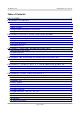
OLIMEX© 2013 STM32-H407 user's manual CHAPTER 8 SCHEMATICS 8. Introduction to the chapter In this chapter are located the schematics describing logically and physically STM32-H407. 8.1 Eagle schematic STM32-H407 schematic is visible for reference here. You can also find them on the web page for STM32-H407 at our site: https://www.olimex.com/Products/ARM/ST/STM32-H407/. They are located in HARDWARE section. The EAGLE schematic is situated on the next page for quicker reference.
130 120 94 83 61 51 16 38 107 3.3V_A 3 3.3V 2 1 B0_1/B0_0 HN1x3(B0_1:Open;B0_0:Close) 33 AREF_EN 1 C28 C29 10uF/6.3V 100nF 2 R16 AREF 32 C30 15R Close 100nF 31 VBAT R17 3.3V U6 NA T 1107A-6_3.8_2.5 10k/1% 2 VCC RESET 1 3 GND C31 23 C32 1k 27pF 100nF 3.
OLIMEX© 2013 STM32-H407 user's manual 8.2 Physical dimensions Note that all dimensions are in millimeters. The three highest elements on the board in order from the tallest to the shortest are: capacitor C46 – 17.2mm (0.677'') over the pcb; USB host connectors – 14.3mm (0.563''); capacitors C11 and C3 – 11.5mm (0.453''). Note that the above measures does not include the PCB.
OLIMEX© 2013 STM32-H407 user's manual CHAPTER 9 REVISION HISTORY AND SUPPORT 9. Introduction to the chapter In this chapter you will find the current and the previous version of the document you are reading. Also the web-page for your device is listed. Be sure to check it after a purchase for the latest available updates and examples. 9.1 Document revision Revision, Date Changes Modified Page# A, 20.07.12 Initial Creation All B, 25.07.
OLIMEX© 2013 STM32-H407 user's manual 9.3 Useful web links and purchase codes The web page you can visit for more info on your device is https://www.olimex.com/Products/ARM/ST/STM32-H407/. You can get the latest updates on the software at: https://github.com/OLIMEX/STM32F4.
OLIMEX© 2013 STM32-H407 user's manual 9.3 Product support For product support, hardware information and error reports mail to: support@olimex.com. All document or hardware feedback is welcome. Note that we are primarily a hardware company and our software support is limited. Please consider reading the paragraph below about the warranty of Olimex products. All goods are checked before they are sent out.