
User manual


I
2
C:
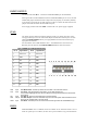
STM32F103RBT6 have two I²C bus interfaces which can operate in multi-master and slave
modes. They can support
standard and fast modes. They support dual slave addressing (7-bit only) and both 7/10-bit
addressing in master
mode. A hardware CRC generation/verification is embedded.
They can be served by DMA and they support SM Bus 2.0/PM Bus.
I2C1.SDA – pin.59 PB7 EXT1-15
I2C1.SCL – pin.58 PB6 EXT1-13
I2C1.SMBA – pin.57 PB5 EXT1-12
I2C2.SDA – pin.30 PB11 EXT2-15
I2C2.SCL – pin. 29 PB10 EXT2-14
I2C2.SMBA – pin.33 PB12 EXT2-17
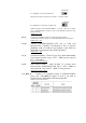
CAN:
The STM32F103RBT6 CAN is compliant with specifications 2.0A and B (active) with a bit
rate up to 1 Mbit/s. It can receive and transmit standard frames with 11-bit identifiers as well
as extended frames with 29-bit identifiers. It has three transmit mailboxes, two receive
FIFOs with 3 stages and 14 scalable filter banks.
The CAN and USB share same pins PA11/EXT1-1 and PA12/EXT1-3, so you can’t use both
CAN and USB on same time.
Pin #
Signal Name
1 GND
2 CANL
3 CANH
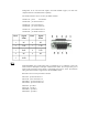
USB:
The STM32F103RBT6 embeds a USB device peripheral compatible with the USB Full-
speed 12 Mbs. The USB interface implements a full speed (12 Mbit/s) function interface. It
has software configurable endpoint setting and suspend/resume support. The dedicated 48
MHz clock source is generated from the internal main PLL.
The CAN and USB share same pins PA11/EXT1-1 and PA12/EXT1-3, so you can’t use both
CAN and USB on same time.