
User manual

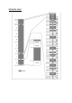


JUMPER DESCRIPTION:
R-T Connects JTAG TRST signal to STM32F103RBT6 RESET
Default state closed (shorted)
BAT_E Connects 3.3V to STM32F103RBT6 Vbat pin.1
Default state closed (shorten), Vbat signal is also available to BAT_3V
connector, so if you want to connect external backup battery to the
STM32F103RBT6 this jumper should be opened (unshorted) and the
external battery to be connected to BAT_3V connector(see connector
description for BAT_3V connector pining.).VBAT accept 2 - 3.6V.
USBP-E Connects USB power supply to STM32F103RBT6 pin.24 PC4/ADC14 and
allow to detect if the board is connected to USB host.
Default state closed (shorten)
LED-E Connects STATUS LED to STM32F103RBT6 pin.53 PC12
Default state closed (shorten)
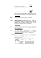
BOOT0, BOOT1 boot sequence select
B1_H/B1_L (Boot1_High/Boot1_Low)
B0_H/B0_L (Boot0_High/Boot0_Low)
B1_H/B1_L
Default position: Boot1 is log. 0
B0_H/B0_L
Boot0 is log. 0
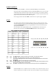
CAN0_T Connect 120 Ohm terminator between CAN_L and CAN_H
busses.
Default state closed (shorten)
CNTRL/HS
CNTRL/HS
1. CNTRL/HS jumper is open
10 KOhm resistor is connected to slope control pin of SN65HVD230 CAN
driver i.e. 15V/uS driver output signal slop.