
User manual

OLIMEX© 2013 TMS320-XDS100v3 user's manual
CHAPTER 4 INTERFACES AND HARDWARE
4. Introduction to the chapter
In this chapter the connectors function will be pointed, the LEDs will be explained, as well as the
jumpers.
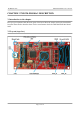
4.1 Connectors
There are five connectors on this board. 3 of them are explained below. The USB connector is type
mini and the small testpads for CT-RXD-GND-RTS-RXD-3/30V is named at the silk.
Note that both JTAG layouts follows the TI specification (which is different than ARM JTAG).
Please refer to the table that can be found at the following web address:
http://processors.wiki.ti.com/index.php/JTAG_Connectors#Pinout
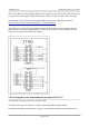
4.1.1 JTAG
The JTAG connector (note the one WITHOUT _14 suffix) gets handy when the device is used as
adapter for older devices. It is also used to upload.
4.1.2 JTAG_14
Used for 14-pin JTAG connection. The JTAG_14 follows the JTAG layout of Texas Instruments.
This interface might be used to communicate with Olimex TMS320-P28016 and Olimex TMX320-
P28027. The interface might be used with any target that follows the 14-pin TI JTAG layout.
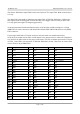
The signals found on the 14-pin TI JTAG might be used for standard 20-pin ARM JTAG connection
if you follow the table below.:
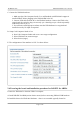
4.1.3 JTAG_20
Used for 20-pin JTAG connection. The JTAG_20 follows the JTAG layout of Texas Instruments.
Note that the step is different from the original JTAG connector. The original connector has a 0.05''
step connector, while the one used by Olimex has 0.1''.
You can lead the signals from this connector to an ARM JTAG layout connector with a small
adapter board or jumper wires. The singnal connection is described below
Page 12 of 16