
User manual
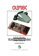

OLIMEX© 2013 TMS320-XDS100v3 user's manual
CHAPTER 2 SETTING UP THE TMS320-XDS100v3
2. Introduction to the chapter
This section helps you set up the TMS320-XDS100v3 emulator/adapter for the first time.
Please consider first the electrostatic warning to avoid damaging the board, then discover the
hardware and software required to operate the board.
The procedure to power up the board is given, and a description of the default board behavior is
detailed.
2.1 Electrostatic warning
TMS320-XDS100v3 is shipped in a protective anti-static package. The board must not be exposed
to high electrostatic potentials. A grounding strap or similar protective device should be worn when
handling the board. Avoid touching the component pins or any other metallic element.
2.3 Requirements
In order to set up the TMS320-XDS100v3 optimally, the following items are required:
- USB-A to mini-USB cable
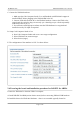
- Set of software tools (preferably Code Composer Studio 5 – check the table -
http://processors.wiki.ti.com/index.php/XDS100#XDS100_Installation_Instructions)
- a TARGET from the supported list (can be found here:
http://processors.wiki.ti.com/index.php/XDS100#XDS100v3_Features)
Note that there are two ribbon cables included in the package – for the JTAG_14 and the JTAG_20
connectors.
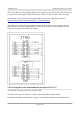
After 01.02.2014 we also started including an adapter that makes the TI JTAG_20 connector
compatible with ARM 20pin JTAG connectors. If you lack such cable you might make it yourself
as described below.
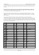
2.4 Cables, layouts, connection
Initially there might be a slight confusion for the proper cable setup which is caused by the number
of different connectors you might meet working with Texas Instruments ARM processors.
Generally, TI works with 14pin JTAG and 20pin JTAG layouts. These layouts are different by the
standards suggested by ARM. Texas Instruments JTAG layout is not the same as ARM JTAG
layout.
XDS100v3 debuggers manufactured after 01.02.2014 also include and ARM JTAG adapter.
Page 6 of 16