
User manual
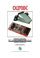

OLIMEX© 2013 TMS320-XDS100v3 user's manual
The Olimex XDS100v3 14pin JTAG has the exact layout of TI's 14pin JTAG. Both connector have
0.1'' step.
The 20pin JTAG that might be found near the 14pin JTAG of TMS320-XDS100v3. It follows the
same signal layout of the original TI XDS100v3 but it uses bigger connector with pin holes with
0.1'' step again (the original TI design suggests 0.05'').
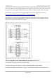
As already mentioned boards manufactured after 01.02.2014 also include an adapter to a 20 pin
ARM JTAG for easier connection with boards like Stellaris EKS-LM3S3748 that have only ARM
JTAG connector.
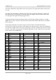
If your target board lacks a TI layout connector and your board was manufactured before
01.02.2014 you would need to make a small adapter or use jumper wires to connect the XDS100v3
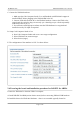
to it. Refer to the table below for the proper connections. The first 4 columns represent the TI layout
of JTAG_14 and JTAG_20 connectors of TMS320-XDS100v3, the last 2 show how to connect their
wires to achieve 20 pin ARM JTAG.
Pin# 14 pin TI Pin# 20 pin TI Pin# 20 pin ARM
1 TMS 1 TMS 7 TMS
2 TRSTn 2 TRSTn 3 TRSTn
3 TDI 3 TDI 5 TDI
4 GND 4 GND 4 GND
5 VTRef 5 VTRef 1 & 2 3.3V (VTRef)
6 NA* 6 NA* 6 GND
7 TDO 7 TDO 13 TDO
8 GND 8 GND 8 GND
9 NA* 9 NA* 11 RTCK
10 GND 10 GND 10 GND
11 TCK 11 TCK 9 TCK
12 GND 12 GND 12 GND
13 EMU0 13 EMU0 NA* NA*
14 EMU1 14 EMU1 NA* NA*
15 15 SRSTn 15 SRSTn
16 16 GND 16 GND
17 17 NA* NA* NA*
18 18 NA* NA* NA*
19 19 NA* NA* NA*
20 20 GND 20 GND
Page 7 of 16