RW400G Router OLITEC User's Guide
Chapter 2: Introduction...................................................................................................... 1 2.1 Overview of the Router ........................................................................................ 1 2.2 Features............................................................................................................... 1 2.3 Panel Layout ........................................................................................................ 2 2.3.
5.10.2 Oray.net DDNS ...................................................................................... 42 5.10.3 Comexe.cn DDNS.................................................................................. 43 5.11 System Tools .................................................................................................... 44 5.11.1 Time ....................................................................................................... 45 5.11.2 Firmware .....................................
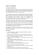
Chapter 2: Introduction 2.1 Overview of the Router The RW400G Wireless Router integrates 4-port Switch, firewall, NAT-router and Wireless AP. Its design is dedicated to Small Office/Home Office (SOHO) wireless network solutions. The RW400G Wireless Router will allow you to connect your network wirelessly better than ever, sharing Internet Access, files and fun, easily and securely. In the most attentive wireless security, the RW400G Wireless Router provides multiple protection measures.
¾ ¾ ¾ ¾ ¾ ¾ ¾ restricted access policies based on the time of day for children or staff Supports TCP/IP, PPPoE, DHCP, ICMP, NAT, SNTP Supports UPnP, Dynamic DNS, Static Routing, VPN pass-through Supports Traffic Statistics Supports ICMP-FLOOD, UDP-FLOOD, TCP-SYN-FLOOD filter Ignores Ping packets from WAN or LAN ports Supports firmware upgrade Supports Remote and Web management 2.3 Panel Layout 2.3.
hold the default reset button then turn on the router's power, until the system LED lights up (about 3 seconds). Last, release the reset button and wait for the router to reboot. Note: Ensure the router is powered on before it restarts completely.
Chapter 3: Connecting the Router 3.1 System Requirements ¾ ¾ ¾ ¾ ¾ Broadband Internet Access Service (DSL/Cable/Ethernet) One DSL/Cable modem that has an RJ45 connector (you do not need it if you connect the router to Ethernet) Each PC on the LAN needs a working Ethernet Adapter and an Ethernet cable with RJ45 connectors TCP/IP protocol must be installed on each PC Web browser, such as Microsoft Internet Explorer 5.0 or later, Netscape Navigator 6.0 or later 3.
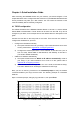
WAN 1 2 3 4 RESET To WAN To LAN Switch/Hub (XDSL、Cable、Ethernet) Figure 3-1: Hardware Installation of the RW400G Wireless Router -5-
Chapter 4: Quick Installation Guide After connecting the RW400G Router into your network, you should configure it. This chapter describes how to configure the basic functions of your RW400G Wireless Router. These procedures only take you a few minutes. You can access the Internet via the router immediately after successfully configured. 4.1 TCP/IP configuration The default IP address of the RW400G Wireless Router is 192.168.1.1, and the default Subnet Mask is 255.255.255.0.
If the result displayed is similar to that shown in figure 4-1, the connection between your PC and the router has been established. Figure 4-2: Failed result of Ping command If the result displayed is similar to that shown in figure 4-2, it means that your PC has not connected to the router. Please check it following these steps: 1. Is the connection between your PC and the router correct? Note: The Link/Act LEDs of LAN port on the router and LEDs on your PC's adapter should be lit. 2.
Figure 4-4 Login Windows Note: If the above screen does not prompt, it means that your web-browser has been set to a proxy. Go to Tools menu>Internet Options>Connections>LAN Settings, in the screen that appears, cancel the Using Proxy checkbox, and click OK to finish it. If the User Name and Password are correct, you can configure the router using the web browser. Please click the Quick Setup link on the left of the main menu and the Quick Setup screen will appear.
Figure 4-7 ¾ Quick Setup - PPPoE User Name and Password - Enter the User Name and Password provided by your ISP. These fields are case sensitive. If you have difficulty with this process, please contact your ISP. If you choose " Dynamic IP", the router will automatically receive the IP parameters from your ISP without needing to enter any parameters.
In this page, you can configure the following wireless parameters: ¾ Wireless Radio - indicates whether the Access Point feature of the router is enabled or disabled. If disabled, the WLAN LED on the front panel will not be lit and the wireless stations will not be able to access the router. If enabled, the WLAN LED will be lit up and wireless stations will be able to access the router. ¾ SSID - Enter a value of up to 32 characters. The same SSID must be assigned to all wireless devices on your network.
Chapter 5: Configuring the Router This chapter describes each web page's key functions. 5.1 login After your successful login, you can configure and manage the router. There are ten main menus on the left of the web-based utility. Submenus will be available after you click one of the main menus. The ten main menus are: Status, Quick Setup, Network, Wireless, DHCP, Forwarding, Security, Static Routing, DDNS and System Tools.
Figure 5-1: Router Status 5.3 Quick Setup Please refer to Section 4.2: "Quick Installation Guide." 5.4 Network Figure 5-2: the Network menu There are three submenus under the Network menu (shown in figure 5-2): LAN, WAN and MAC Clone. Click any of them, and you will be able to configure the corresponding function. The detailed explanations for each submenu are provided below.
5.4.1 LAN You can configure the IP parameters of LAN on this page. Figure 5-3: LAN ¾ MAC Address - the physical address of the router, as seen from the LAN. The value can't be changed. ¾ IP Address - Enter the IP address of your router in dotted-decimal notation (factory default: 192.168.1.1). ¾ Subnet Mask - An address code that determines the size of the network. Normally use 255.255.255.0 as the subnet mask. Note: a.
Figure 5-4 WAN – Dynamic IP This page displays the WAN IP parameters assigned dynamically by your ISP, including IP address, Subnet Mask, Default Gateway, etc. Click the Renew button to renew the IP parameters from your ISP. Click the Release button to release the IP parameters. MTU Size: The normal MTU (Maximum Transmission Unit) value for most Ethernet networks is 1500 Bytes. For some ISPs you need to reduce the MTU.
Figure 5-4a: WAN - 802.1X + Dynamic IP User Name - Enter the user name for 802.1x authentication provided by your ISP ¾ Password - Enter the password for 802.1x authentication provided by your ISP. Click Login button to start 802.1x authentication. Click Logout button to end 802.1x authentication. ¾ 2. If you choose Static IP, you should have fixed IP Parameters specified by your ISP.
If you are also given a user name and a password for 802.1x authentication, you should select 802.1x + Static IP for WAN Connection Type, a box will then appear requesting a user name and a password, shown in figure 5-5a: Figure 5-5a: WAN - 802.1X + Static IP ¾ ¾ User Name - Enter the user name for 802.1x authentication provided by your ISP Password - Enter the password for 802.1x authentication provided by your ISP. Click Login to start 802.1x authentication. Click Logout to end 802.1x authentication.
Caution: Sometimes the connection cannot be disconnected although you specify a time to Max Idle Time, since some applications is visiting the Internet continually in the background. ¾ Connect Automatically - Connect automatically after the router is disconnected. To use this option, click the radio button. ¾ Time-based Connecting - You can configure the router to make it connect or disconnect based on time.
it is necessary for your ISP. ¾ Service Name/AC Name - The service name and AC (Access Concentrator) name, this should not be done unless you are sure it is necessary for your ISP. ¾ ISP Specified IP Address - If you know that your ISP does not automatically transmit your IP address to the router during login, click “Use the IP Address specified by ISP” check box and enter the IP Address in dotted-decimal notation, which your ISP provided.
5.5 Wireless Figure 5-9: Wireless menu There are three submenus under the Wireless menu (shown in figure 5-9): Wireless Settings, MAC Filtering and Wireless Statistics. Click any of them, and you will be able to configure the corresponding function. The detailed explanations for each submenu are provided below. 5.5.1 Wireless Settings The basic settings for the wireless network are set on this page, figure 5-10: Figure 5-10: Wireless Settings ¾ SSID - Enter a value of up to 32 characters.
wireless function of the router in a region other than one of those specified in this field. If your country or region is not listed, please contact your local government agency for assistance ¾ Channel - This field determines which operating frequency will be used. It is not necessary to change the wireless channel unless you notice interference problems with another nearby access point. ¾ Mode - Select the desired wireless mode. The options are: • 54Mbps (802.11g) - Both 802.11g and 802.
Hexadecimal format stands for any combination of hexadecimal digits (0-9, a-f, A-F) in a specified length. ¾ WEP Key settings - Select which of the four keys will be used and enter the matching WEP key information for your network in the selected key radio button. These values must be identical on all wireless stations in your network. ¾ Key Type - You can select the WEP key length (64-bit, or 128-bit, or 152-bit) for encryption. "Disabled" means the WEP key entry is invalid.
5.5.2 MAC Filtering The Wireless MAC Filtering for wireless networks are set on this page, figure 5-11: Figure 5-11: Wireless MAC address Filtering The Wireless MAC Address Filtering feature allows you to control wireless stations accessing the router, which depend on the station's MAC addresses. ¾ ¾ ¾ ¾ ¾ MAC Address - The wireless station's MAC address that you want to access. Description - A simple description of the wireless station. Privilege - Allow means allowing the station to access the router.
Figure 5-12: Add or Modify Wireless MAC Address Filtering entry To add or modify a MAC Address Filtering entry, follow these instructions: 1. Enter the appropriate MAC Address into the MAC Address field. The format of the MAC Address is XX-XX-XX-XX-XX-XX (X is any hexadecimal digit). For example: 00-0A-EB-B0-00-0B. 2. Enter a simple description of the wireless station in the Description field. For example: Wireless station A. 3. 4.
1. Click the Enable button to enable this function. 2. Select the radio button: Deny the stations not specified by any enabled entries in the list to access for Filtering Rules. 3. Delete all or disable all entries if there exist any entries already. 4. Click the Add New... button and enter the MAC address 00-0A-EB-00-07-BE in the MAC Address field, enter wireless station A in the Description field, select Allow in the Privilege pull-down list and select Enabled in the Status pull-down list.
Figure 5-13: The router attached wireless stations ¾ ¾ ¾ ¾ MAC Address - The connected wireless station's MAC address Current Status - The connected wireless station's running status, one of STA-AUTH / STA-ASSOC / AP-UP / WPA / WPA-PSK /WPA2/WPA2-PSK/None Received Packets - packets received by the station Sent Packets - packets sent by the station You cannot change any of the values on this page. To update this page and to show the current connected wireless stations, click on the Refresh button.
¾ DHCP Server - Enable or Disable the DHCP server. If you disable the Server, you must have another DHCP server within your network or else you must manually configure the computer. ¾ Start IP Address - This field specifies the first of the addresses in the IP address pool. 192.168.1.100 is the default start address. ¾ End IP Address - This field specifies the last of the addresses in the IP address pool. 192.168.1.199 is the default end address.
5.6.3 Address Reservation When you specify a reserved IP address for a PC on the LAN, that PC will always receive the same IP address each time when it accesses the DHCP server. Reserved IP addresses should be assigned to servers that require permanent IP settings. This page is used for address reservation (shown in figure 5-17). Figure 5-17: Address Reservation ¾ MAC Address - The MAC address of the PC of which you want to reserve IP address.
Note: The function won't take effect until the router reboots. 5.7 Forwarding Figure 5-18: the Forwarding menu There are four submenus under the Forwarding menu (shown in figure 5-18): Virtual Servers, Port Triggering, DMZ and UPnP. Click any of them, and you will be able to configure the corresponding function. The detailed explanations for each submenu are provided below. 5.7.1 Virtual Servers Virtual servers can be used for setting up public services on your LAN, such as DNS, Email and FTP.
protocols supported by the router). ¾ ¾ Enable - The Enable checkbox to enable the virtual server entry. Common Service Port - Some common services already list in the pull-down list. To setup a virtual server entry: 1. Select the service you want to use from the Common Service Port list, and select the ID you want to use, and click Copy to button. If the Common Service Port list does not have the service that you want to use, type the number of the service port 2. 3. 4. 5.
Figure 5-20: Port Triggering Once configured, operation is as follows: 1. A local host makes an outgoing connection using a destination port number defined in the Trigger Port field. 2. The router records this connection, opens the incoming port or ports associated with this entry in the Port Triggering table, and associates them with the local host. 3. When necessary the external host will be able to connect to the local host using one of the ports defined in the Incoming Ports field.
4. 5. 6. Select the protocol used for Incoming Ports Range from the pull-down list, either TCP or UDP, or All. Select the Enable checkbox to enable. Click the Save button to save the new rule. There are many popular applications in the Popular Application list. You can select it and the ID, then click the Copy to button, the application will fill in the Trigger Port, incoming Ports Range boxes and select the Enable checkbox. It has the same effect as adding a new rule. Modifying an existing rule: 1.
To assign a computer or server to be a DMZ server: 1. 2. 3. Click the Enable radio button Enter the local host IP Address in the DMZ Host IP Address field Click the Save button. Note: After you set the DMZ host, the firewall related to the host will not work. 5.7.4 UPnP The Universal Plug and Play (UPnP) feature allows the devices, such as Internet computers, to access the local host resources or devices as needed. UPnP devices can be automatically discovered by the UPnP service application on the LAN.
5.8 Security Figure 5-23: the Security menu There are six submenus under the Security menu (shown in figure 5-23): Firewall, IP Address Filtering, Domain Filtering, MAC Filtering, Remote Management and Advanced Security. Click any of them, and you will be able to configure the corresponding function. The detailed explanations for each submenu are provided below. 5.8.1 Firewall Using the Firewall page (shown in figure 5-24), you can turn the general firewall switch on or off.
¾ Enable MAC Filtering - set MAC Address Filtering is enabled or disabled. You can select the default filtering rules of MAC Address Filtering, either Allow or Reny accessing the router. 5.8.2 IP Address Filtering The IP address Filtering feature allows you to control Internet Access by specific users on your LAN based on their IP addresses.
Keep the field open, which means all LAN IP Addresses have been put into the field. 3. LAN Port - type a LAN Port or a range of LAN ports in the field. For example, 1030 2000. Keep the field open, which means all LAN ports have been put into the field. 4. WAN IP Address - type a WAN IP Address or a range of WAN IP Addresses in the field, in dotted-decimal notation format. For example, 61.145.238.6 – 61.145.238.47. Keep the field open, which means all WAN IP Addresses have been put into the field. 5.
Figure 5-27: Domain Filtering Before adding a Domain Filtering entry, you must ensure that Enable Firewall and Enable Domain Filtering have been selected on the Firewall page. To Add a Domain filtering entry, click the Add New… button. The page " Add or Modify a Domain Filtering entry " will appear, shown in figure 5-28: Figure 5-28: Add or Modify a Domain Filtering entry To add or modify a Domain Filtering entry, follow these instructions: 1.
Click the Next button to go to the next page and the Previous button to return to the previous page. For example, if you want to block the PCs on your LAN to access websites www.xxyy.com.cn, www.aabbcc.com and websites with .net in the end on the Internet while no limit for other websites, you should specify the following Domain filtering list: 5.8.
To add or modify a MAC Address Filtering entry, follow these instructions: 1. Enter the appropriate MAC Address into the MAC Address field. The format of the MAC Address is XX-XX-XX-XX-XX-XX (X is any hexadecimal digit). For example: 00-0E-AE-B0-00-0B. 2. Type the description of the PC in the Description field. Fox example: John’s PC. 3. Status - Select Enabled or Disabled for this entry on the Status pull-down list. 4. Click the Save button to save this entry. To add additional entries, repeat steps 1-4.
¾ Web Management Port - Web browser access normally uses the standard HTTP service port 80. This router’s default remote management web port number is 80. For greater security, you can change the remote management web interface to a custom port by entering that number in this box provided. Choose a number between 1024 and 65534, but do not use the number of any common service port. ¾ Remote Management IP Address - This is the current address you will use when accessing your router from the Internet.
¾ ¾ Packets Statistic interval (5 ~ 60) - The default value is 10. Select a value between 5 and 60 seconds in the pull-down list. The Packets Statistic interval value indicates the time section of the packets statistic. The result of the statistic used for analysis by SYN Flood, UDP Flood and ICMP-Flood. DoS protection - Enable or Disable the DoS protection function. Only when it is enabled, will the flood filters be effective.
¾ ¾ Host IP Address- The IP address that blocked by DoS are displayed here. Host MAC Address - The MAC address that blocked by DoS are displayed here. To update this page and to show the current blocked host, click on the Refresh button. Click the Clear All button to clear all displayed entries. After the table is empty the blocked host will regain the capability to access Internet. Click the Return button to return to the Advanced Security page 5.
To delete all the entries: 1. Click the Clear All button. 2. Click the Save button. Note: You can set up to 8 entries. 5.10 DDNS The router offers a Dynamic Domain Name System (DDNS) feature. DDNS lets you assign a fixed host and domain name to a dynamic Internet IP Address. It is useful when you are hosting your own website, FTP server, or other server behind the router. Before using this feature, you need to sign up for DDNS service providers such as www.dyndns.org, www.oray.net or www.comexe.cn.
Figure 5-36: Oray.net DDNS Settings To set up for DDNS, follow these instructions: 1. 2. 3. Type the User Name for your DDNS account. Type the Password for your DDNS account. Click the Login button to login the DDNS service. ¾ Connection Status - the status of the DDNS service connection is displayed here. ¾ Domain Name - the domain names are displayed here. Click Logout to logout the DDNS service. 5.10.3 Comexe.cn DDNS If your selected dynamic DNS Service Provider is www.comexe.cn.
Figure 5-37: Comexe.cn DDNS Settings To set up for DDNS, follow these instructions: 5. 6. 7. 8. ¾ Type the domain names your dynamic DNS service provider gave. Type the User Name for your DDNS account. Type the Password for your DDNS account. Click the Login button to login to the DDNS service. Connection Status -The status of the DDNS service connection is displayed here. Click Logout to logout of the DDNS service. 5.
5.11.1 Time You can set time manually or get GMT from the Internet for the router on this page (shown in figure 5-39): Figure 5-39: Time settings ¾ ¾ ¾ Time Zone - Select your local time zone from this pull down list. Date - Enter your local date in MM/DD/YY into the right blanks. Time - Enter your local time in HH/MM/SS into the right blanks. Time setting follows these steps below: 1. Select your local time zone. 2. Enter date and time in the right blanks 3. Click Save.
If the router is not experiencing difficulties, there is no need to download a more recent firmware version, unless that version has a new feature that you want to use. Note: When you upgrade the router's firmware, you may lose its configuration settings, so make sure you write down the router settings before you upgrade its firmware. To upgrade the router's firmware, follow these instructions: 1. Download a more recent firmware upgrade file. 2.
Figure 5-42: Reboot the router Click the Reboot button to reboot the router. Some settings of the router will take effect only after rebooting, which include: • • • • • • • Change LAN IP Address. (System will reboot automatically) MAC Clone (system will reboot automatically) DHCP service function. Static address assignment of DHCP server. Web Service Port of the router. Upgrade the firmware of the router (system will reboot automatically).
5.11.6 Log This page (shown in figure 5-44) allows you to query the Logs of the router. Figure 5-44: System Log The router can keep logs of all traffic. You can query the logs to find what happened to the router. Click the Refresh button to refresh the logs. Click the Clear Log button to clear all the logs. 5.11.7 Statistics The Statistics page (shown in figure 5-45) displays the network traffic of each PC on LAN, including total traffic and traffic of the last Packets Statistic interval seconds.
IP Address Total Packets The total amount of packets received and transmitted by the router. Bytes The total amount of bytes received and transmitted by the router. Packets Bytes Current The IP Address displayed with statistics ICMP Tx UDP Tx The total amount of packets received and transmitted in the last Packets Statistic interval seconds. The total amount of bytes received and transmitted in the last Packets Statistic interval seconds.
Appendix A: FAQ 1. How do I configure the router to access Internet by ADSL users? 1) 2) First, configure the ADSL modem configured in RFC1483 bridge model. Connect the Ethernet cable from your ADSL modem to the WAN port on the router. The telephone cord plugs into the Line port of the ADSL modem. Login to the router, click the “Network” menu on the left of your browser, and click "WAN" submenu. On the WAN page, select “PPPoE” for WAN Connection Type.
MAC register, login to the router and click the "Network" menu link on the left of your browser, and then click "MAC Clone" submenu link. On the "MAC Clone" page, if your PC’s MAC address is proper MAC address, click the "Clone MAC Address" button and your PC’s MAC address will fill in the "WAN MAC Address" field. Or else, type the MAC Address into the " WAN MAC Address" field. The format for the MAC Address is XX-XX-XX-XX-XX-XX. Then click the "Save" button. It will take effect after rebooting.
Figure A-5 4. DMZ I want to build a WEB Server on the LAN, what should I do? 1) 2) Because the WEB Server port 80 will interfere with the WEB management port 80 on the router, you must change the WEB management port number to avoid interference. To change the WEB management port number: Login to the router, click the “Security” menu on the left of your browser, and click "Remote Management" submenu.
Figure A-7 5. Virtual Server The wireless stations cannot connect to the router. 1) 2) 3) 4) Make sure the "Wireless Router Radio" is enabled. Make sure that the wireless stations' SSID accord with the router's SSID. Make sure the wireless stations have right KEY for encryption when the router is encrypted. If the wireless connection is ready, but you can’t access the router, check the IP Address of your wireless stations.
Appendix B: Configuring the PCs In this section, we’ll introduce how to install and configure the TCP/IP correctly in Windows 95/98. First make sure your Ethernet Adapter is working, refer to the adapter’s manual if needed. 1. Install TCP/IP component 1) 2) 3) On the Windows taskbar, click the Start button, point to Settings, and then click Control Panel. Double-click the Network icon, click on the Configuration tab in the appearing Network window. Click on the Add button.
Figure B-3: Configuration tab 3) 4) • Click on Properties. The following TCP/IP Properties window will display and the IP Address tab is open on this window by default. Now you have two ways to configure the TCP/IP protocol below: Assigned by DHCP Sever a. Select Obtain an IP address automatically, as shown in the figure below: Figure B-4: IP Address tab b. Do not type anything into the New gateway field on the Gateway tab.
Figure B-5: Gateway tab c. Choose Disable DNS on the DNS configuration tab, as shown in the following figure: Figure B-6: DNS Configuration tab • Setting IP address manually a. Select Specify an IP address on IP Address tab, as shown in the following figure. If the router's LAN IP address is 192.168.1.1, type IP address is 192.168.1.x (x is from 2 to 254), and subnet mask is 255.255.255.0.
Figure B-7: IP Address tab b. Type the router’s LAN IP address (the default IP is 192.168.1.1) into the New gateway field on the Gateway tab, and click on the Add button, as shown in the figure: Figure B-8: Gateway tab c. On the DNS Configuration tab, click Enable DNS radio, and type your computer name in to the Host field and a Domain (such as szonline.com) into the Domain field.
click Add button. Shown below: Figure B-9: DNS Configuration tab Now, all the configurations are finished, it will take effect after reboot.
Appendix C: Specifications General Standards IEEE 802.3, 802.3u, 802.11b and 802.11g Protocols TCP/IP, PPPoE, DHCP, ICMP, NAT, SNTP Ports One 10/100M Auto-Negotiation WAN RJ45 port, Four 10/100M Auto-Negotiation LAN RJ45 ports supporting Auto MDI/MDIX Cabling Type 10BASE-T: UTP category 3, 4, 5 cable (maximum 100m) EIA/TIA-568 100Ω STP (maximum 100m) 100BASE-TX: UTP category 5, 5e cable (maximum 100m) EIA/TIA-568 100Ω STP (maximum 100m) Radio Data Rate 54/48/36/24/18/12/9/6Mbps or 11/5.
Appendix D: Glossary ¾ 108M Super GTM WLAN Transmission Technology - 108M Super GTM WLAN Transmission Technology employs multiple performance-enhancing techniques including packet bursting, fast frames, data compression, and dynamic turbo mode that combine to improve the throughput and range of wireless networking products. Users can experience link rates of up to 108Mbps, twice the industry-standard maximum data link rate of 54Mbps, while preserving full compatibility with traditional 802.11g or 802.
¾ Domain Name - A descriptive name for an address or group of addresses on the Internet. ¾ DoS (Denial of Service) - A hacker attack designed to prevent your computer or network from operating or communicating. ¾ DSL (Digital Subscriber Line) - A technology that allows data to be sent or received over existing traditional phone lines. ¾ ISP (Internet Service Provider) - A company that provides access to the Internet.