OWNER’S MANUAL FOR PCR/AR RIFLES 620-626 Old Pacific Hwy SE Olympia, WA 98513 (360) 459-7940
WARNING To avoid accidental firing, BE SURE WEAPON IS CLEAR. Failure to do so could result in serious injury or death. Be sure the cam pin is installed in the bolt group. If it isn’t, your rifle can still fire and will explode causing injury or death. DO NOT exchange or switch bolt assemblies from one AR-15 to another. It could cause damage to both you and your rifle. DON’T OVERHEAT YOUR AR-15 BARREL. Sustained firing of the AR-15 will rapidly raise the temperature of the barrel to a critical point.
Table of Contents Technical Principles of Operation, AR-15 4 Operating Instructions Description and Use of Operator’s Controls 5 Sight Adjustments 6 Magazine Insertion and Loading 8 9 Chambering and Firing Clearing Your AR-15 Operation Under Unusual Conditions Field Stripping Hand Guards - The “Buddy System” 10 12 13 13 Maintenance of Upper Receiver and Barrel Assembly 17 Maintenance of Charging Handle Assembly and Bolt Carrier Assembly 18 Maintenance of Lower Receiver and Extension Assembly
Technical Principles of Operation NOTE: Magazine may be loaded with bolt assembly open or closed. 1. Place selector on SAFE 2. Insert loaded cartridge magazine in magazine well and chamber a round. 3. Face the target, move the selector lever from SAFE to FIRE and place the rifle to your shoulder. 4. Align the front and rear sight with the target and squeeze the trigger. 5. Squeezing the trigger releases the firing pin and allows it to impact the primer on the round. 6.
Operating Instructions Description and Use of Operator’s Controls and Indicators MECHANICAL CONTROLS REAR SIGHT (1) - zeroes weapon and engages targets to 460 meters. HAND GUARD SLIP RING (2) - keeps hand guards in place. FLASH SUPPRESSOR (3) - reduces the amount of flash from muzzle when weapon is fired. EJECTION PORT COVER (4) - protects upper receiver from foreign matter when weapon is not in use. Keep port cover closed when not used. CARTRIDGE MAGAZINE (5) - supplies ammunition to weapon.
Sight Adjustments - A-l Type RIFLE SIGHTS (ZERO ADJUSTMENT) - Move front (1) and rear (2) sights to make sure they can be adjusted. Return sights to zero setting of your rifle. DUMMY REAR SIGHT - To adjust windage, depress detent and rotate drum to direction you want: 1. To move point of impact to right, turn drum clockwise in direction of arrow and letter R. 2. To move left, move drum counterclockwise..*a), 3. Each notch moves the point of impact of bullet as indicated in chart.
Sight Adjustments - A-2 Type (cont’d) ADJUSTABLE REAR SIGHT HAS TWO APERTURES FOR RANGE SHORT RANGE (O-200 METERS) NORMAL RANGE (300-800 METERS) 2. SHORT RANGE - The “larger” aperture is used for O-200 meters range. As shown, the sight is set for O-200 meters. This larger aperture is only used when the rear sight is all the way down - the 300-meter mark is aligned with the mark on the left side of the receiver. BATTLESIGHT ZERO When battlesights are on your rifle: , 1.
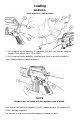
Loading WARNING Point muzzle in a safe direction \ 1. Pull charging handle assembly (1) rearward, lock bolt, and release charging handle. Place selector lever (2) on SAFE. 2. Pull charging handle assembly rearward and check to see that chamber is clear. Release charging handle assembly. NOTE Magazine may be loaded with bolt assembly open or closed. Push upward on cartridge magazine (3) until magazine catch (4) engages and holds cartridge magazine.
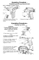
Operating Procedure Chambering and Firin 1. Depress upper portion of bolt catch (1) to release the bolt 2. Tap forward assist assembly (2) to ensure bolt is fully forward and locked. 3. Move selector lever (3) to FIRE. 4. Squeeze the trigger (4) and fire. BOLT ASSEMBLY CLOSED 1. Place the selector lever (1) on FIRE 2. Pull charging handle assembly (2) all the way back. 3. Release the charging handle assemblv i (2). 4. Never “ride” the charging handle assemblv (2). Let it go on its own. ” i ..
Operating Procedure Chambering and Firing a Round (Cont.) BOLT ASSEMBLY CLOSED (CONT.) 5. Tap forward assist assembly (3) to ensure bolt is fully forward and locked. 6. Squeeze the trigger (4) and fire. Operating Procedures Clearing Your Rifle WARNING To avoid accidental firing, always look into chamber after clearing weapon to make sure it does not contain a round. 1. Place selector lever (1) on SAFE. NOTE If weapon is not cocked, lever cannot be pointed toward SAFE. 2.
Operating Procedures Clearing Your Rifle (Cont.) NOTE Ensure that selector lever (1) is on SAFE. 4. Check receiver and chamber (6) to ensure these areas contain no ammunition. 5. With selector lever (1) pointing toward SAFE, allow bolt to go forward by pressing upper portion of bolt catch (5). NOTE If weapon is to be stored, it should be dry fired to release tension on hammer spring. 6. Place selector lever (1) on FIRE and squeeze trigger to release tension on hammer spring.
Operation Under Unusual Conditions NOTE Unusual conditions are defined as any climatic condition requiring special maintenance of the weapon. Perform the maintenance outlined for the climate that most applies to your operational area. HOT, DRY CLIMATES NOTE Hot, dry climates are usually dusty and sandy areas. They are hot during daylight hours and cool during the night hours. A.
Maintenance Procedures Field-stripping Your AR-15 CLEARING RIFLE WARNING To avoid accidental firing, be sure rifle is SLING HAND GUARDS THE “BUDDY SYSTEM” 1. Remove and clean hand guards only if dirt and corrosion can be seen through hand guard vent holes. 2. Place the weapon on the buttstock (I) with one hand gripping the stock and the other gripping the lower end of the hand guard (2). 3.
CHARGING HANDLE ASSEMBLY AND BOLT CARRIER ASSEMBLY 1. Pull back charging handle assembly (1) and bolt carrier assembly (2). 2. Remove bolt carrier assembly (2). 3. Pull charging handle assembly (1) back and down and remove it. 4. Move bolt assembly (3) forward to unlocked position and remove firing pin retaining pin (4). Do not open or close split end of firing pin retaining pin (4). 5. Push in on bolt assembly (3) to put in locked position.
CHARGING HANDLE ASSEMBLY AND BOLT CARRIER ASSEMBLY (Cont.) 6. Catch firing pin (5) as it drops out of rear of bolt carrier assembly (2). 7. Give bolt cam pin (6) a l/4 turn and lift out. 8. Remove bolt assembly (3) from bolt carrier assembly (2). 9. Press top of extractor (7) to check that spring works. NOTE Disassemble extractor and spring asassembly only when dirty or damaged. 10. Use round (5) to remove extractor pin (8).
CHARGING HANDLE ASSEMBLY AND BOLT CARRIER ASSEMBLY (Cont.) CAUTION Do not separate insert from spring assembly (9). 11. Remove extractor (7) and spring assembly (9). Do not remove spring assembly (9) from extractor (7). QJ [ jL:& qfjp7 LOWER RECEIVER AND EXTENSION ASSEMBLY 1. Press in buffer (1) and depress retainer (2) to release buffer. 2. Remove buffer (1) and spring (3). CAUTION No further disassembly is advisable.
Maintenance Procedures Maintenance of Upper Receiver and Barrel Assembly CLEANING NOTE Don’t reverse direction of bore brush while it is in the bore. Use cleaner, lubricant and preservative (CLP) on the following areas: A. All areas of powder fouling, corrosion, dirt and rust. B. Bore and chamber. C. Upper receiver and barrel assembly locking lugs. D. Gas tube. 1. Use cleaning rod, bore brush, and CLP. Run rod through chamber (2) and flash 2.
Maintenance of Upper Receiver and Barrel Assembly (Cont.) LUBRICATION 1. Lightly lubricate bore and chamber, outer surface of barrel and front sight, and surfaces under hand guards. 2. Start at receiver (1) and go right through the flash suppressor (2). Don’t reverse directions in bore. 3. Lubricate locking lugs (3). 4. Depress front sight detent (4) several times to work CLP into the spring using a round (5).
MAINTENANCE OF CHARGING HANDLE ASSEMBLY AND BOLT CARRIER ASSEMBLY (Cont.) 3. Remove carbon deposits and dirt from locking lugs (3) with bore brush dipped in CLP. 4. Clean areas behind bolt rings (4) and under lip of extractor (5). INSPECTION WARNING DO NOT interchange bolt assemblies between rifles. 1. Inspect charging handle assembly (1) for cracks, bends, or breaks. 2. Inspect bolt assembly (2) for cracks and fractures, especially in the cam pin hole area. 3.
LUBRICATION (Cont.) a 9 CARRIER KEY 3. Dry inside key of bolt carrier assembly (8). Place one drop of CLP inside kev. CLEANING 4. Lightly lubricate with CLP inner and outer surfaces of bolt carrier assembly (8). Generously lubricate slide (9) and cam pin area (10) of bolt carrier assembly (8). 5. Lightly lubricate charging handle assembly (II). CAUTION Do not use steellwire brush or any type of abrasive material to clean aluminum surfaces. L 1. Wipe dirt from trigger (1) with a swab. 3.
Maintenance of Lower Receiver and Extension Assembly INSPECTION 1. Examine lower receiver and extension assembly (1) for broken or bent trigger (2), buttstock (3), corroded or deformed lower receiver (l), cracked or damaged rifle grip (4), and bent or damaged selector lever (5). Look at inside parts of lower receiver and extension assembly (1) for cracks, dents, or breaks. 2. If you think the parts are bad, see a reputable gunsmith. LUBRICATION 1.
Reassembly of AR-15 Rifle LOWER RECEIVER AND EXTENSION ASSEMBLY Insert spring (1) and buffer (2). BOLT CARRIER ASSEMBLY AND CHARGING HANDLE ASSEMBLY NOTE New extractor has silicone insert with spring. Be sure not to lose it. 1. If the spring comes loose, seat the large end of spring in the extractor. 2. Insert extractor (1) and spring assembly (2) into bolt. 3. Push extractor (1) and spring assembly (2) down. Align hole (3) with hole in bolt and insert extractor pin (4). 4.
REASSEMBLY (Cont.) 7. Drop firing pin (9) in opening and seat. 8. Pull bolt assembly (6) back and replace firing pin retaining pin (10) NOTE Firing pin should not fall out when bolt carrier assembly is turned upside down. - \ Y / 9. Turn bolt carrier assembly (7) over and try to shake out firing pin. 10. Engage, then push, charging handle assembly (11) part way into upper receiver.
REASSEMBLY (Cont.) Bolt Carrier Assembly and Charging Handle Assembly NOTE Be sure bolt assembly is extended from bolt carrier. 1 1. Slide bolt carrier assembly (7) into upper receiver. 12. Push charging handle assembly (11) and bolt carrier assembly (7) together into upper receiver (12). JOINING UPPER AND LOWER RECEIVERS 1. Join upper receiver (1) and lower receiver (2). 2. Align the pivot pin holes and push pivot pin (3) in. CAUTION Selector lever must be on SAFE before closing upper receiver. 3.
REASSEMBLY (Cont.) Joining Upper and Lower Receivers CAUTION Ejection port cover must be closed before closing upper and lower receiver to prevent damage to cover. 4. Close ejection port cover (5). 5. Close upper receiver (1) and lower receiver (2). Push in takedown pin (6). HAND GUARDS - THE “BUDDY SYSTEM 1. Place the weapon on the buttstock (1) with one hand gripping the stock and the other gripping the lower end of the barrel. Insert hand guard into hand guard cap (2). 2.
FUNCTIONAL CHECK WARNING To avoid accidental firing, be sure cartridge magazine is removed and chamber is clear. 1. Pull charging handle assembly (1) to rear and release. Place selector lever (2) on SAFE. Squeeze trigger (3). Hammer should not fall. 2. Place selector lever (2) on FIRE. Squeeze trigger (3); hammer should fall. Hold trigger to the rear. Pull charging handle assembly (1) to rear and release. Release trigger (3). You should hear a click as you release the trigger.