INSTRUCTIONS DP12 MICROSCOPE DIGITAL CAMERA SYSTEM This instruction manual is for the Olympus DP12 Microscope Digital Camera System. To ensure the safety, obtain optimum performance and familiarize yourself fully with the use of this system, we recommend that you study this manual thoroughly before operating the system. Retain this instruction manual in an easily accessible place near the work desk for future reference.
DP12 CONTENTS IMPORTANT 1-2 — Be sure to read this section for safe use of the equipment. — 1 SYSTEM CHART 2 NOMENCLATURE 3 ASSEMBLY 4 DIGITAL IMAGE PHOTOGRAPHING/RECORDING PROCEDURE 5 BASIC OPERATIONS .................................................................. 3 4-7 8-11 12 13-16 15 13 2 One-Touch White Balance (OTWB) .......... 14 3 Checking the Live Image ........................................ 14 4 Playing a Single Picture (PLAY) .......................
7 MONITOR DISPLAY OF PICTURES 1 8 Monitor Observation in Record Mode ..... 32 32 2 Monitor Observation in Play Mode ......... PICTURE DOWNLOADING IN A PERSONAL COMPUTER 33 3 Playing Pictures on a PC ........................................ 35 1 Connecting a PC ................................................................ 32 33-36 2 Loading Pictures .................................................................
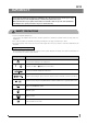
DP12 IMPORTANT Connecting this digital camera system to an Olympus UIS or LB series microscope allows you to easily photograph and record the magnified images observed through the microscope. When the DP12 microscope digital camera adapter is used with a microscope from other manufacturer than Olympus, the optical performance may not be manifested fully. SAFETY PRECAUTIONS 1. Use the provided AC adapter only.
1 Getting Ready 1. The camera system uses precision components. Handle it with care and avoid subjecting it to a sudden or severe impact. 2. The image displayed on the liquid crystal display may be affected when it is used near equipment generating strong electromagnetic waves. This is not a malfunction and will not affect the actual image being recorded. To avoid interference during operation, keep the system far from any source of electromagnetic waves. 3.
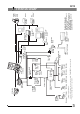
SZX series BX/BX2 series MX series Double port U-DPT TV lens U-TV1X-2 0.5X TV lens U-TV0.5X AX series TV zoom lens U-TVZ C-mount adapter U-CMAD-3 DP12 control box Film recorder* Printer* Digital printer P-400 P-200 Windows is a registered trademark of Microsoft Corporation. All other brand and product names are registered trademarks or trademarks of their respective owners. The camera file system standard employed is the DCF format.
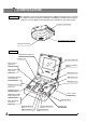
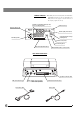
NOMENCLATURE Any equipment connected to the camera unit should be an Olympus-specified product or a product in compliance with the requirements of IEC60950 or CISPR22/24. If equipment other than these products is connected, Olympus cannot guarantee proper performance of the camera system. Camera Unit Control box connector (P. 9) Tripod adapter mount screw hole Threaded C-mount (P. 8) Control Box AE LOCK indicator LED (P. 18) LCD panel (P. 6) LCD monitor (Next page) SPOT metering button (P.
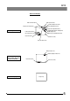
DP12 On-Screen Display Write protect (P. 16) Print reservation (P. 19) Picture quality mode (P. 21) Recording pixels (P. 23) Compression rate (P. 23) Recording Information Folder name (P. 24) Exposure adjustment (P. 17) Manual white balance setting (P. 21) ISO rating (P. 22) File name (P. 24) Microscope magnification (P. 26) Date/Time (P. 23) Frame No. (P. 14) Exposure time (P. 13) Write protect (P. 16) Picture quality mode (P.
LCD Panel Details }The LCD panel shows setup and error information individually. However, for ease of explanation, the LCD panel in this page is shown with all of its display segments lit up. Number of remaining pictures (P. 21)/ Error code display (P. 37) Card error (P. 37) Exposure time (P. 13) Picture quality mode (P. 21) Center-weighted average metering (P. 17) ISO rating (P. 22) Camera mode (P. 13) Spot metering (P. 17) Exposure adjustment (P. 17) Manual white balance control (P.
DP12 SmartMedia (SSFDC) M-32PI (32 MB) Write protect area }The M-2P (2 MB),. M-4P (4 MB), M-8P (8 MB), M-16PI (16 MB), M-64PI (64 MB) and M-128PI (128 MB) SmartMedia can also be used with the DP12. (Note) For details, refer to the instruction manual provided with your SmartMedia. Index area Write protect seal sheet Static protection case Index labels Contact area # The SmartMedia is a precision device. Handle it with care and avoid subject it to sudden or severe impact.
ASSEMBLY This chapter pertains only to installation and assembly of the DP-12 microscope digital camera system. For instructions on how to assemble the microscope system and TV adapter being used with the camera system, refer to the appropriate instruction manuals. 1 2 Attaching the Camera Unit (Figs. 1 & 2) Screw the U-TV0.5XC C-mount adapter 1 into the threaded C-mount on the bottom of the camera unit 2.
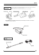
DP12 2 2 Attaching the Control Box (Fig. 3) 1 1. Insert the connector ³ on the end of the connection cable with the ferrite core | into the rear of the control box and tighten the clamping screw on the connector. 2. Insert the connector @ on the other end of the connection cable into the connector ² on the camera unit and tighten the clamping screw on the connector. 3 4 Fig. 3 2 3 1 3 4 Fig. 4 Attaching the AC Adapter (Fig. 4) # Always be sure to use the provided AC adapter.
To unplug the AC adapter Set the main switch of the control box to “ ” (OFF), remove the AC adapter’s output connector 3 from the control box then remove the power cord’s plug from the power outlet. CAUTION Always use a power supply with the specified voltage. Do not operate the camera system when any of the connectors and plugs of the AC adapter and power cord is not completely inserted. Never insert or remove the power cord’s plug or connector with a wet hand.
DP12 4 1 Inserting (Removing) the SmartMedia (Fig. 5) # Make sure the main switch is set to “ " (OFF) before insertion. # A 3.3 V SmartMedia card manufactured by Olympus or marketed in stores can be used. However, when using a non-Olympus 3.3 V SmartMedia, it may be necessary to format it (see page 29). # A 5 V SmartMedia marketed in stores cannot be used with this camera system. 1. Open the card cover 1. 2.
DIGITAL IMAGE PHOTOGRAPHING/ RECORDING PROCEDURE · Perform all necessary optical adjustments on the microscope. (The camera system can photograph and record microscopic images under transmitted and reflected light illumination as well as other observation techniques except fluorescence microscopy.) · Use the TV adapter to perform the confocal adjustment between the microscope’s eyepieces and the LCD monitor image. Insert a SmartMedia. (P. 11) Set the main switch of the control box to “ I ” (ON).
DP12 BASIC OPERATIONS }After installing the SmartMedia, press the main switch 1 of the control box to turn it ON. (Fig. 7) 2 1 Fig. 7 Fig. 8 · The LCD panel shown in Fig. 8 shows the setup before turning power ON and the number of remaining pictures 2 in the current picture quality mode (see page 21). · After turning the camera system ON, first set the current and date and time (see page 23). # When the number of remaining pictures becomes , “ ” and “ ” on the LCD panel blink.
2 One-Touch White Balance (OTWB) (Fig. 10) }Apart from the OTWB, the white balance can also be controlled with manual white balance control, which sets the color temperature by direct input (see page 21). 1. Press the MODE button 1 to select REC MANU. or REC AUTO. 2. Press the OTWB button 2 to display the white photographing screen. 3. In transmitted light observation, remove the specimen so that the entire screen is white. In reflected light observation, use a sheet of white paper as the specimen.
DP12 5 @ ³ ² Fig. 13 Zooming a Played Picture (Fig. 13) }When a single picture is pressed, press the MOVE button 1 or 2 to zoom the played picture in the order as shown below. (The initial image magnification is 1X.) : 1/16X 1/9X 1/4X 1X 2X 4X : 4X 2X 1X 1/4X 1/9X 1/16X }At 1/9X, for example, nine played pictures are displayed are simultaneously. Meanwhile, at 2X and 4X, for example, the entire picture cannot be displayed in the LCD monitor screen.
6 ² Protecting a Picture (PROTECT) (Fig. 14) }The following procedure is used to protect a picture against accidental erasure. 1. Press the MODE button to select PLAY. 2. Press either MOVE button or 1 to select the picture to be protected. 3. Press the PROTECT button 2. The picture being displayed is protected and green protect marking is shown at the top right of the picture. @ · It is also possible to protect a picture displayed with zooming.
DP12 SPECIAL FUNCTIONS 6-1 Setup Using the Control Box 1 Setting the Spot Metering (SPOT) (Fig. 16) }The camera system measures light using the center-weighted average method when the spot metering method is not used. · Center-weighted average metering: Generally employed photometry method which measures light in a wide range centered around the field center. · Spot metering: This photometry method measures only the light at the center of the LCD monitor.
3 @ 4 Fig. 19 18 (Fig. 18) }By moving the slide position with the average specimen distribution at the center and locking the exposure time, the following effects can be achieved. · Even when a specimen is recorded by varying the compositional arrangement many times, the specimen area can always be recorded with an optimum exposure. · When a linked picture like panoramic photo is created, the joints between pictures are not noticeable when their exposure is constant. 1.
DP12 5 ² @ | ³ Fig. 20 Making a Print Reservation (PRINT) (Fig. 20) }Print reservation/cancellation of all picture frames, date and time can be set by means of a menu (see pages 30 and 31). 1. Press the MODE button 1 to select PLAY. 2. Display the picture to be subjected to print reservation, and then press the PRINT reservation button 2. 3. The LCD monitor shows the number of printouts.
6-2 Setup/Operation Using Menus (MENU) }By displaying a menu on the LCD monitor, the functions of the system can be set up or run through the menus. The displayed menus are variable in the record modes (REC MANU, REC AUTO) and play (PLAY) mode. Basic Concept of Menu Setup (Fig. 21) Setting item Setting options Page select markings The pressed-in status indicates that the option in question is selected. Cursor (The set item is enclosed by green frame .) Press the MENU button 1.
DP12 6-2-1 Function Setup in Record Modes · Select REC MANU or REC AUTO with the MODE button. · Press the MENU button to display a menu on the LCD monitor. · After setting, be sure to press the SET/OK button to establish the setting. 1 Setting the White Balance (WB) Factory setup: AUTO }The one-touch white balance setting is also available using the OTWB button on the control box (see page 14).
3 Setting the ISO Rating (ISO) Factory setup: 25 }The sensitivity (ISO rating) in recording can be set like a photo film. The provided ISO values are set by converting the obtained sensitivity into an ISO value of photography films. ISO rating Three ISO values including 25, 50 and 100 are available. A larger value indicates that the camera becomes more suitable for recording under low light or recording of quickly moving objects. · When an other value than “25” is selected, the LCD panel shows “ISO”.
DP12 7 Setting the Date/Time Factory setup: —— }The date and time can be set in the camera system. The recording date and time are recorded together with pictures. Time Month-Day-Year, Year-MonthDay or Day-Month-Year Select the order of the figures of year, month and day. · After selecting , press either MOVE button or to select the order of the figures of year, month and day. · When the order of figures has been set, the display becomes , where the figures which can be set nor are displayed in green.
10 Setting the File and Folder Names Factory setup: RESET }The file and folder of a picture recorded with the DP12 are named respectively as file No. 0001 to 9999 and folder No. 100 to 999. The file and folder can be named by one of the two methods including AUTO and RESET. These options can be selected from item FILE MENU in the menu. Folder and file names A picture recorded with the DP12 is given a folder name and file name as shown below.
DP12 11 Displaying the Metering Range Factory setup: OFF }This item sets whether or not the metering area in the spot and center-weighted average modes is to be displayed on the LCD monitor. 12 Setting the Color Picture Display Factory setup: COLOR }This item sets whether a color picture or monochrome picture is displayed. The monochrome option is applied to the recorded pictures as well as to the live images.
Scale display position setting Factory setup: }This item sets the position of the scale display. (Select either the vertical scale display or horizontal scale display.) Horizontal scale (Vertical) Horizontal scale display Vertical scale display LCD monitor Vertical scale Microscope magnification input/setting Factory setup: ON1/0001.00 }This item is used to input the microscope magnification data, which is required when displaying the scale. A magnification value between 0000.00 and 9999.
DP12 15 Setting the Focusing Indicator Display Factory setup: OFF }This item is used to display the focusing condition of the incident light as a reference in focusing. The focusing indicator is displayed as a bar at the bottom right of the LCD monitor screen. Initial display This is the status immediately after this item is set to ON. Neither the current level nor the maximum level are indicated.
16 Setting the Monitor Brightness Factory setup: —— }The brightness of the monitor can be adjusted by moving the indicator to the left or right. Brightness indicator 17 Setting the Video Output Factory setup: NTSC }Set this item to the specified video output for your system. 18 Resetting the Recording Setups }The setups related to recording can be reset to the factory defaults. This function is used when you have forgotten the setups you made previously.
DP12 6-2-2 Function Setup and Operations in Play Mode · Press the MODE button to select PLAY. · Press the MENU button to display a menu on the LCD monitor. · After setting, be sure to press the SET/OK button to establish the setting. 1 Setting the Auto Playback Display Factory setup: —— }This item displays pictures by advancing them frame by frame, just like a slide show. Frame by frame advance every 5 sec.
3 Printing }Pictures recorded in a SmartMedia can be printed out on a printer. 1. Press the MODE button to select PLAY. 2. Press the MENU button to display a menu on the LCD monitor. 3. After setting, be sure to press the SET/OK button to establish the setting. Setting Printing The following methods are available for printing pictures which have been recorded with this camera system and in a SmartMedia.
DP12 Index print reservation }Print reservation of all pictures in the SmartMedia selected at the time of reservation in the form of indexes is also possible. Cancel Reservation ON · Pictures recorded after index print reservation are not covered by the index print reservation. If there are nonreserved pictures in a SmartMedia, the “ ! ” marking appears next to menu item “CARD INDEX”. To make index print reservation of all pictures, restart the setting from the beginning.
MONITOR DISPLAY OF PICTURES }The recorded pictures can be displayed on a video monitor by using the provided video cable. This makes it possible to view the pictures on a large screen even when a PC is not available. Before connecting the cable, be sure to set the main switch of the control box to “ ” (OFF) and also turn off the video monitor. 1. Connect the video cable 1 to the video output connector 2 on the control box. 2.
DP12 PICTURE DOWNLOADING IN A PERSONAL COMPUTER The recorded pictures can be downloaded in a PC using optional image processing software. In this chapter, the method for connecting the DP12 to a PC and that for downloading images into the PC using the CDROM provided with the DP12-BSW PC connection kit. 1 Connecting a PC }When the DP12 is connected to a PC using the optional DP12-BSW PC connection kit, the picture data can be downloaded directly from the SmartMedia installed in the DP12 to the PC.
2 Loading Pictures {Loading using the software in CD-ROM To download recorded pictures to the PC through a USB cable for displaying them on or saving them in the PC, install the software in the CD-ROM provided with the optional DP12-BSW in your PC. The following functions are available with the software in the CD-ROM. For installation and operation, refer to the on-line manual of the software. Communication with camera Picture files in the camera system can be downloaded to the PC through a USB cable.
DP12 3 Playing Pictures on a PC }To view recorded pictures on a PC screen, use the software in the CD-ROM provided with the optional DP12-BSW PC connection kit. {Playback of pictures recorded in a SmartMedia }Pictures recorded in the SmartMedia installed in the camera system can be viewed using the DP12-BSW. 1. Start the software installed in the PC. 2. Click the “My Camera” icon. The list of recorded pictures appears. 3. Place the cursor on the picture you want to view and double-click it.
{Loading of pictures recorded in a SmartMedia on the PC Pictures recorded in the SmartMedia installed in the camera system can be loaded in the PC. 1. Start the software installed in the PC. 2. Select [Camera] in the menu bar then select [Download All Images]. All pictures in the SmartMedia are loaded from it to the PC.
DP12 ERROR CODE LIST }The DP12 displays warnings in the form of error codes. (The display in the LCD panel of the control box blinks during display.) LCD Panel LCD Monitor (PLAY mode only) Error Details Treatment The card cover is open. Insert a SmartMedia and close the card cover. CARD ERROR Data in the SmartMedia cannot be recorded, played or erased. If the SmartMedia is dirty, wipe with cleaning paper before insertion or format it. If this error occurs again, the SmartMedia is not usable.
10 SPECIFICATIONS Specification Item Type C-mount CCD camera unit & control box Image pickup device 1/1.8-inch, 3.34 million pixels (3.24 million pixels effective). RGB primary color on-chip filters. Effective pixels: 2088(H) x 1550(V) pixels CCD camera Sensitivity: ISO 25/50/100 equivalent. Photometry methods: Center-weighted average method (30% in center), spot metering method (1% in center). Exposure control: AUTO, MANUAL, AE LOCK. Exposure time: AUTO (1/2 to 1/4000 sec.
11 TROUBLESHOOTING GUIDE DP12 Under certain conditions, the performance of the camera system may be adversely affected by factors other than defects. If problems occur, please review the following list and take remedial action as needed. If you cannot solve the problem after checking the entire list, please contact your local Olympus representative for assistance. Trouble Cause a) The control box does not work. The main switch of the control box is not ON. Set the main switch to “ I ” (ON).
Trouble Cause f ) Picture is too dark or bright. AE LOCK, EXP.ADJ. and/or SPOT are not set properly. Set them properly. The illumination brightness is not set properly. Adjust the brightness. A fluorescent lamp is in use. Use an illumination other than a fluorescent lamp. g) The colors in the picture are strange. A wrong color temperature is set in the white balance control operation. Set the color temperature properly. h) Error message is displayed during data downloading to PC.
DP12 PROPER SELECTION OF THE POWER SUPPLY CORD If no power supply cord is provided, please select the proper power supply cord for the equipment by referring to “ Specifications ” and “ Certified Cord ” below: CAUTION: In case you use a non-approved power supply cord for Olympus products, Olympus can no longer warrant the electrical safety of the equipment.
Table 2 HAR Flexible Cord APPROVAL ORGANIZATIONS AND CORDAGE HARMONIZATION MARKING METHODS Approval Organization Printed or Embossed Harmoniza- Alternative Marking Utilizing tion Marking (May be located on Black-Red-Yellow Thread (Length jacket or insulation of internal wir- of color section in mm) ing) Black Red Yellow Comite Electrotechnique Belge (CEBEC) CEBEC 10 30 10 Verband Deutscher Elektrotechniker (VDE) e.V.
2-43-2,Hatagaya, Shibuya-ku, Tokyo, Japan Postfach 10 49 08, 20034, Hamburg, Germany 2 Corporate Center Drive, Melville, NY 11747-3157, U.S.A. 491B River Valley Road, #12-01/04 Valley Point Office Tower, Singapore 248373 2-8 Honduras Street, London EC1Y OTX, United Kingdom. 104 Ferntree Gully Road, Oakleigh, Victoria, 3166, Australia This publication is printed on recycled paper.
DP12 Simplified Operation Manual AX6272 Recording Procedure Main Factory Settings Insert SmartMedia @. · Picture quality mode: HQ · Exposure correction: ±0 Set the main switch ² to “ I ” (ON). · White balance control: AUTO · Metering mode: Center average Set the REC AUTO mode. Press the MODE button ³ to move · Sharpness: NORMAL to · ISO: 25 indicate “REC AUTO”.) }For the settings enabling various recording techSet the light path selector of the microscope to the photomicrography (TV) light path.
DP12 Simplified Operation Manual Playback Procedure AX6272 Erasure Procedure }A protected picture cannot be erased. Insert SmartMedia @. (Use prerecorded SmartMedia.) }When a write protect sticker is attached to SmartMedia, the pictures recorded in it cannot be erased. Set the main switch ² to “ I ” (ON). Set the PLAY mode. Press the MODE button ³ to move All-picture erasure to indi- cate “PLAY”. To play a single picture: Press the MOVE button picture.