Macro Flash System / Makro-Blitz-System System de flash gros plan / Sistema de flash macro Macro Flash Controller FC-1 Ring Flash RF-11 / Twin Flash TF-22 Makro-Blitz-Steuerung FC-1 Ringblitz RF-11 / Zweifachblitz TF-22 Controleur de flash en gros plan FC-1 Flash annulaire RF-11 / Flashes jumeaux TF-22 Controlador de flash para macro FC-1 Flash de anillo RF-11 / Flash doble TF-22 Instructions Bedienungsanleitung 2 53 Mode d’emploi 107 Instrucciones 161
Thank you for purchasing the OLYMPUS Macro Flash System. Before use, please read this instruction manual to ensure your safety, and keep it handy for future reference. SAFETY PRECAUTIONS (Be sure to read and observe the following.) This instruction manual uses a variety of common symbols and icons to assist you in proper handling and usage of this product, and to warn you of potential hazards to yourself and others as well as to property. These symbols and their significance are described below.
Thank you for purchasing the OLYMPUS Macro Flash System. Before use, please read this instruction manual to ensure your safety, and keep it handy for future reference. SAFETY PRECAUTIONS (Be sure to read and observe the following.) This instruction manual uses a variety of common symbols and icons to assist you in proper handling and usage of this product, and to warn you of potential hazards to yourself and others as well as to property. These symbols and their significance are described below.
All rechargeable batteries must be recharged using the specified battery charger, simultaneously and completely. Be sure to read the battery and battery charger instruction manual. HANDLING PRECAUTIONS The Macro Flash System is composed of precision electronic parts. Absolutely avoid using or storing the Macro Flash System in the following places, as this may result in malfunction or failure. • Under direct sunlight, on a beach, etc.
All rechargeable batteries must be recharged using the specified battery charger, simultaneously and completely. Be sure to read the battery and battery charger instruction manual. HANDLING PRECAUTIONS The Macro Flash System is composed of precision electronic parts. Absolutely avoid using or storing the Macro Flash System in the following places, as this may result in malfunction or failure. • Under direct sunlight, on a beach, etc.
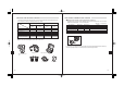
CONTENTS • Macro Flash System ...................................................................................................................... 7 • Checking the Package Contents ................................................................................................... 8 • Applicable Cameras and Lenses ................................................................................................... 9 • Nomenclature ..............................................................................
CONTENTS • Macro Flash System ...................................................................................................................... 7 • Checking the Package Contents ................................................................................................... 8 • Applicable Cameras and Lenses ................................................................................................... 9 • Nomenclature ..............................................................................
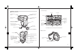
CHECKING THE PACKAGE CONTENTS APPLICABLE CAMERAS AND LENSES Check that all of the parts and accessories shown in the following table are included in the package. If any item is missing or damaged, contact your dealer.
CHECKING THE PACKAGE CONTENTS APPLICABLE CAMERAS AND LENSES Check that all of the parts and accessories shown in the following table are included in the package. If any item is missing or damaged, contact your dealer.
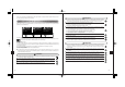
NOMENCLATURE Control Panel Display Macro Flash Controller FC-1 Twin Flash Ring Flash connector (Page 15) Control mode Ring Flash release button (Page 15) Ring Flash Twin Flash connector (B) (Page 27) Twin Flash release button (Page 28) Twin Flash connector (A) (Page 27) Twin Flash light ratio display (Pages 36& 40) Guide number (GN) Light intensity adjustment (Pages 21, 23, 35 & 39) Lock ring Setting display (GN, light intensity and light intensity adjustment) External power connector Connect th
NOMENCLATURE Control Panel Display Macro Flash Controller FC-1 Twin Flash Ring Flash connector (Page 15) Control mode Ring Flash release button (Page 15) Ring Flash Twin Flash connector (B) (Page 27) Twin Flash release button (Page 28) Twin Flash connector (A) (Page 27) Twin Flash light ratio display (Pages 36& 40) Guide number (GN) Light intensity adjustment (Pages 21, 23, 35 & 39) Lock ring Setting display (GN, light intensity and light intensity adjustment) External power connector Connect th
Twin Flash TF-22 MACRO FLASH CONTROLLER FC-1 Connector terminal (Page 27) Light emitting Diffuser FDT-1 window (Page 41) Diffuser mounting groove Tripod screw Shoe ring mount (Page 41) (TF-22 flash section) Mounting ring Rotation ring Illuminator (Page 33) Rotation lock button Always use one of the following battery combinations • AA (R6) alkaline dry cell batteries (LR6 type) ...................... • AA (R6) Ni-Cd batteries ......................................................
Twin Flash TF-22 MACRO FLASH CONTROLLER FC-1 Connector terminal (Page 27) Light emitting Diffuser FDT-1 window (Page 41) Diffuser mounting groove Tripod screw Shoe ring mount (Page 41) (TF-22 flash section) Mounting ring Rotation ring Illuminator (Page 33) Rotation lock button Always use one of the following battery combinations • AA (R6) alkaline dry cell batteries (LR6 type) ...................... • AA (R6) Ni-Cd batteries ......................................................
RING FLASH RF-11 Confirm that both the camera and Macro Flash Controller are off. Attaching or removing the Macro Flash Controller while either it or the camera is on may result in malfunction. How to attach • Attach the FC-1 Macro Flash Controller to the camera beforehand. • To prevent the Ring Flash from falling off, attach it with the camera in a stable position. 1.
RING FLASH RF-11 Confirm that both the camera and Macro Flash Controller are off. Attaching or removing the Macro Flash Controller while either it or the camera is on may result in malfunction. How to attach • Attach the FC-1 Macro Flash Controller to the camera beforehand. • To prevent the Ring Flash from falling off, attach it with the camera in a stable position. 1.
MACRO FLASH CONTROLLER FC-1 1. Turn the camera on and then press the Power button to MACRO FLASH CONTROLLER FC-1 MODE LAMP AUTO CHECK TEST/ CHARGE LIGHT RATIO GN/ POWER turn the Ring Flash on. • The [RING] indicator appears on the control panel and battery charging starts. MODE LAMP blinks, wait until the blinking stops, then turn the camera off and re-connect the Ring Flash to the Ring Flash connector (page 47).
MACRO FLASH CONTROLLER FC-1 1. Turn the camera on and then press the Power button to MACRO FLASH CONTROLLER FC-1 MODE LAMP AUTO CHECK TEST/ CHARGE LIGHT RATIO GN/ POWER turn the Ring Flash on. • The [RING] indicator appears on the control panel and battery charging starts. MODE LAMP blinks, wait until the blinking stops, then turn the camera off and re-connect the Ring Flash to the Ring Flash connector (page 47).
1. Press the Shutter button of the camera gently to start comMACRO FLASH CONTROLLER FC-1 MODE LAMP AUTO CHECK TEST/ CHARGE LIGHT RATIO GN/ munication of shooting information including ISO speed, lens iris and shutter speed between the camera and Macro Flash System. • The selected flash control mode is shown on the control panel. • The mode is switched every time the MODE button is pressed.
1. Press the Shutter button of the camera gently to start comMACRO FLASH CONTROLLER FC-1 MODE LAMP AUTO CHECK TEST/ CHARGE LIGHT RATIO GN/ munication of shooting information including ISO speed, lens iris and shutter speed between the camera and Macro Flash System. • The selected flash control mode is shown on the control panel. • The mode is switched every time the MODE button is pressed.
Light intensity adjustment The flash light intensity can be adjusted between +3 and –3. In this mode, pre-flash is performed to measure the optimum flash light intensity and then the actual flash is emitted. 1. See the following table and set the lens iris (F) according MACRO FLASH CONTROLLER FC-1 MODE MACRO FLASH CONTROLLER FC-1 to the lens in use.
Light intensity adjustment The flash light intensity can be adjusted between +3 and –3. In this mode, pre-flash is performed to measure the optimum flash light intensity and then the actual flash is emitted. 1. See the following table and set the lens iris (F) according MACRO FLASH CONTROLLER FC-1 MODE MACRO FLASH CONTROLLER FC-1 to the lens in use.
Light intensity adjustment The light intensity ratio (guide number) can be adjusted in 1/3-step increments. In this mode, the flash is emitted according to the light intensity setting. 1. The control panel shows the light intensity ratio. MACRO FLASH CONTROLLER FC-1 Light intensity ratio: Ratio of the current light intensity with respect to the full flash light intensity.
Light intensity adjustment The light intensity ratio (guide number) can be adjusted in 1/3-step increments. In this mode, the flash is emitted according to the light intensity setting. 1. The control panel shows the light intensity ratio. MACRO FLASH CONTROLLER FC-1 Light intensity ratio: Ratio of the current light intensity with respect to the full flash light intensity.
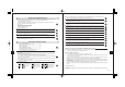
8) 4) 16 4( 1/ 1/ − 2( 1/ − 1/ − 1( 1/ − 2) 1) Light intensity ratio ISO100 (ISO400) (1 / Iris (F) F22 1/ How to read the chart (1 / The following charts show the light control range of the RF-11 Ring Flash with each type of lens. ) ZUIKO DIGITAL 14-54mm f2.8-3.5, At 14 mm < Light control range> 1/8(1/32) 1. TTL AUTO F16 Flash at optimum exposure is available by setting the lens iris (F) in the range for each shooting distance shown in the following charts.
8) 4) 16 4( 1/ 1/ − 2( 1/ − 1/ − 1( 1/ − 2) 1) Light intensity ratio ISO100 (ISO400) (1 / Iris (F) F22 1/ How to read the chart (1 / The following charts show the light control range of the RF-11 Ring Flash with each type of lens. ) ZUIKO DIGITAL 14-54mm f2.8-3.5, At 14 mm < Light control range> 1/8(1/32) 1. TTL AUTO F16 Flash at optimum exposure is available by setting the lens iris (F) in the range for each shooting distance shown in the following charts.
ZUIKO DIGITAL ED50-200mm f2.8-3.5, At 50 mm Iris (F) F22 TWIN FLASH TF-22 Light intensity ratio ISO100 (ISO400) • Attach the FC-1 Macro Flash Controller to the camera beforehand. −−(1/1) F16 1/1(1/4) −−(1/2) F11 1. Attach the SR-1 Shoe Ring (provided) to the lens. 1/2(1/8) 1/1(1/4) F8 1/4(1/16) 1/2(1/8) F5.6 1/8(1/32) 1/4(1/16) F4.0 1/16(1/64) 1/8(1/32) F2.8 Shooting distance 8m 4m 2m 1.2m TTL AUTO light control range, with ISO 100 28cm∼27.
ZUIKO DIGITAL ED50-200mm f2.8-3.5, At 50 mm Iris (F) F22 TWIN FLASH TF-22 Light intensity ratio ISO100 (ISO400) • Attach the FC-1 Macro Flash Controller to the camera beforehand. −−(1/1) F16 1/1(1/4) −−(1/2) F11 1. Attach the SR-1 Shoe Ring (provided) to the lens. 1/2(1/8) 1/1(1/4) F8 1/4(1/16) 1/2(1/8) F5.6 1/8(1/32) 1/4(1/16) F4.0 1/16(1/64) 1/8(1/32) F2.8 Shooting distance 8m 4m 2m 1.2m TTL AUTO light control range, with ISO 100 28cm∼27.
4. Insert the TF-22 Twin Flash connector terminal into the Twin Flash connector on the FC-1 Macro Flash Controller until it clicks. • When unplugging the connectors, be sure to press and hold the Twin Flash release button. Be sure to attach the cap after unplugging the connectors. • Do not pull the cord when plugging or unplugging the connector. Always grasp it by the connector plug. Pulling the cord could damage the connector wire. 1.
4. Insert the TF-22 Twin Flash connector terminal into the Twin Flash connector on the FC-1 Macro Flash Controller until it clicks. • When unplugging the connectors, be sure to press and hold the Twin Flash release button. Be sure to attach the cap after unplugging the connectors. • Do not pull the cord when plugging or unplugging the connector. Always grasp it by the connector plug. Pulling the cord could damage the connector wire. 1.
MACRO FLASH CONTROLLER FC-1 3. Press the Power button again to turn the Twin Flash off. MODE LAMP AUTO CHECK TEST/ CHARGE LIGHT RATIO GN/ POWER Turn the Twin Flash off in the following cases: • Before mounting it on the camera or dismounting it from the camera. • When flash emission is not required. • When not using the Twin Flash. • When plugging or unplugging the Twin Flash connectors. 1.
MACRO FLASH CONTROLLER FC-1 3. Press the Power button again to turn the Twin Flash off. MODE LAMP AUTO CHECK TEST/ CHARGE LIGHT RATIO GN/ POWER Turn the Twin Flash off in the following cases: • Before mounting it on the camera or dismounting it from the camera. • When flash emission is not required. • When not using the Twin Flash. • When plugging or unplugging the Twin Flash connectors. 1.
Angle of light emitting section The illuminators can be used as indicators for three different functions: modeling, AF, and redeye reduction. • Adjustment at the following angles is possible in the up-down direction.
Angle of light emitting section The illuminators can be used as indicators for three different functions: modeling, AF, and redeye reduction. • Adjustment at the following angles is possible in the up-down direction.
Light intensity adjustment The flash light intensity can be adjusted between +3 and –3. In this mode, pre-flash is performed to measure the optimum flash light intensity and then the actual flash is emitted. 1. See the following table and set the lens iris (F) according MACRO FLASH CONTROLLER FC-1 MODE MACRO FLASH CONTROLLER FC-1 LAMP to the lens in use.
Light intensity adjustment The flash light intensity can be adjusted between +3 and –3. In this mode, pre-flash is performed to measure the optimum flash light intensity and then the actual flash is emitted. 1. See the following table and set the lens iris (F) according MACRO FLASH CONTROLLER FC-1 MODE MACRO FLASH CONTROLLER FC-1 LAMP to the lens in use.
Twin Flash light ratio setting When using both flashes ( A and B ), you can adjust the ratio between their light intensities as required. This makes it possible to create a three-dimensional effect by applying various degrees of shading to the subject as shown below. In this mode, the flash is emitted according to the light intensity setting. MACRO FLASH CONTROLLER FC-1 1. The control panel shows the light intensity ratio.
Twin Flash light ratio setting When using both flashes ( A and B ), you can adjust the ratio between their light intensities as required. This makes it possible to create a three-dimensional effect by applying various degrees of shading to the subject as shown below. In this mode, the flash is emitted according to the light intensity setting. MACRO FLASH CONTROLLER FC-1 1. The control panel shows the light intensity ratio.
How to determine the lens iris (F), light intensity or guide number (GN) Since the distance to the subject is very short and the shooting magnification is very high in Macro shooting, the light intensity is lower than would normally be the case with the lens iris (F) setting. This is because the light intensity for the lens iris is based on a distance setting of infinity.
How to determine the lens iris (F), light intensity or guide number (GN) Since the distance to the subject is very short and the shooting magnification is very high in Macro shooting, the light intensity is lower than would normally be the case with the lens iris (F) setting. This is because the light intensity for the lens iris is based on a distance setting of infinity.
Twin Flash light ratio setting When using both flashes ( A and B ), you can adjust the ratio between their light intensities as required. This makes it possible to create a three-dimensional effect by applying various degrees of shading to the subject as shown below. The diffuser enables shooting under soft lighting by attenuating the shades on the subject. Another way that shooting options are increased is the ability to use the wide-open iris (F). 1.
Twin Flash light ratio setting When using both flashes ( A and B ), you can adjust the ratio between their light intensities as required. This makes it possible to create a three-dimensional effect by applying various degrees of shading to the subject as shown below. The diffuser enables shooting under soft lighting by attenuating the shades on the subject. Another way that shooting options are increased is the ability to use the wide-open iris (F). 1.
Light intensity ratio ISO100 (ISO400) − − (1 /2 ) 1/ 1( 1/ 4) 1/ 2( 1/ 8) 1/ 4( 1/ 16 ) 1/ 8( 1/ 32 ) 1/ 16 (1 /6 4 Iris (F) F22 (1 /1 ) The following figures show the light control range of the TF-22 Twin Flash with each type of lens. The figures assume that both flashes are used at the recommended angle (page 32). ) ZUIKO DIGITAL 14-54mm f2.8-3.5, At 14 mm < Light control range> − − 1/32(1/128) 1.
Light intensity ratio ISO100 (ISO400) − − (1 /2 ) 1/ 1( 1/ 4) 1/ 2( 1/ 8) 1/ 4( 1/ 16 ) 1/ 8( 1/ 32 ) 1/ 16 (1 /6 4 Iris (F) F22 (1 /1 ) The following figures show the light control range of the TF-22 Twin Flash with each type of lens. The figures assume that both flashes are used at the recommended angle (page 32). ) ZUIKO DIGITAL 14-54mm f2.8-3.5, At 14 mm < Light control range> − − 1/32(1/128) 1.
Iris (F) F22 Light intensity ratio ISO100 (ISO400) (1 /2 ) 1/ 1( 1/ 4) 1/ 2( 1/ 8) 1/ 4( 1/ 16 ) 1/ 8( 1/ 32 ) Light intensity ratio ISO100 (ISO400) (1 /1 ) Iris (F) F22 ZUIKO DIGITAL 11-22mm f2.8-3.5, At 11 mm − − (1 /1 ) − − (1 /2 ) ZUIKO DIGITAL ED50-200mm f2.8-3.5, At 50 mm − − − − 1/16(1/64) 1/1(1/4) F16 1/4(1/16) F16 1/8(1/32) F11 1/16(1/64) F8 1/32(1/128) 1/2(1/8) F11 1/64(1/256) 1/4(1/16) F8 1/128(1/512) 1/8(1/32) F5.6 1/32(1/128) F5.6 1/64(1/256) F4.
Iris (F) F22 Light intensity ratio ISO100 (ISO400) (1 /2 ) 1/ 1( 1/ 4) 1/ 2( 1/ 8) 1/ 4( 1/ 16 ) 1/ 8( 1/ 32 ) Light intensity ratio ISO100 (ISO400) (1 /1 ) Iris (F) F22 ZUIKO DIGITAL 11-22mm f2.8-3.5, At 11 mm − − (1 /1 ) − − (1 /2 ) ZUIKO DIGITAL ED50-200mm f2.8-3.5, At 50 mm − − − − 1/16(1/64) 1/1(1/4) F16 1/4(1/16) F16 1/8(1/32) F11 1/16(1/64) F8 1/32(1/128) 1/2(1/8) F11 1/64(1/256) 1/4(1/16) F8 1/128(1/512) 1/8(1/32) F5.6 1/32(1/128) F5.6 1/64(1/256) F4.
CUSTOM SETUP ALL RESET Custom setup allows each user to customize flash setup to suit his or her preferences. All Reset resets the custom setups to the factory default settings. Setup procedure MACRO FLASH CONTROLLER FC-1 MACRO FLASH CONTROLLER FC-1 1. Turn the Macro Flash Controller on. LAMP RATIO LAMP MODE AUTO CHECK 2. Press and hold the MODE button for more than 2 seconds, until the setup mode display appears in the control panel.
CUSTOM SETUP ALL RESET Custom setup allows each user to customize flash setup to suit his or her preferences. All Reset resets the custom setups to the factory default settings. Setup procedure MACRO FLASH CONTROLLER FC-1 MACRO FLASH CONTROLLER FC-1 1. Turn the Macro Flash Controller on. LAMP RATIO LAMP MODE AUTO CHECK 2. Press and hold the MODE button for more than 2 seconds, until the setup mode display appears in the control panel.
CONTINUOUS FIRING Continuous firing makes the light-emitting section hot and may cause it to deteriorate or malfunction. Therefore, continuous firing should be limited to the counts shown in the following tables. Do not use the Macro Flash System for at least 10 minutes after continuous firing up to the limit count. OPTIONAL ACCESSORIES Shoe adapter ring • Flash Adapter Ring FR-1 Mounting adapter for use with a Zuiko Digital ED50mmf2.0Macro lens for Olympus Four Thirds System digital cameras.
CONTINUOUS FIRING Continuous firing makes the light-emitting section hot and may cause it to deteriorate or malfunction. Therefore, continuous firing should be limited to the counts shown in the following tables. Do not use the Macro Flash System for at least 10 minutes after continuous firing up to the limit count. OPTIONAL ACCESSORIES Shoe adapter ring • Flash Adapter Ring FR-1 Mounting adapter for use with a Zuiko Digital ED50mmf2.0Macro lens for Olympus Four Thirds System digital cameras.
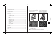
Q&A Q The FC-1 cannot be turned on. A It cannot be turned on in the following cases. • When the connector(s) for the unused flash (either the Ring Flash or Twin Flash) is not capped. • When both the Ring Flash and Twin Flash are connected. Q Is multi-flash shooting possible in the TTL AUTO mode? A No, it is not possible. Q Why does the flash get hot after successive firing? A The batteries generate heat when flash firing is repeated successively.
Q&A Q The FC-1 cannot be turned on. A It cannot be turned on in the following cases. • When the connector(s) for the unused flash (either the Ring Flash or Twin Flash) is not capped. • When both the Ring Flash and Twin Flash are connected. Q Is multi-flash shooting possible in the TTL AUTO mode? A No, it is not possible. Q Why does the flash get hot after successive firing? A The batteries generate heat when flash firing is repeated successively.
Twin Flash TF-22 Model Number Type Guide numbers : FS-TF22 : External flash for digital still camera : Full flash activation: 22 (using 2 flashes) or 16 (using 1 flash). Minimum flash activation : 1.0 (using 2 flashes) or 0.7 (using 1 flash). MANUAL flash activation : 1.0 to 22 (using 2 flashes) or 0.7 to 16 (using 1 flash). Firing angle : Using 1 flash: Up-down 50°, left-right 55° Flash emission period : Approx. 1/1250 sec. Flash emission count : Approx.