Electronic Flash FL-36R Instruction Manual r2067_e_000_cs2j.
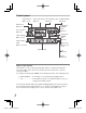
Names of parts Flash Wide panel gP. 24 AF illuminator light-emitting area gP. 28, 34 When the subject is dark or low-contrast, the built-in AF illuminator emits light to facilitate focusing. Light-emitting area Remote sensor gP. 35 Auto light receptor gP. 16 Lock pin gP. 9 Lock ring gP. 9 Electric contacts gP. 9 Checking the package contents The following items are included with the electronic flash. If anything is missing or damaged, contact the dealer from whom you purchased the electronic flash.
Bounce lock release button (left-right direction) gP. 9, 22 Bounce up/down angle indices gP. 22 Bounce lock release button (up-down direction) gP. 9, 22 Bounce left/right angle indices gP. 22 Accessory shoe AUTO CHECK lamp gP. 12 MODE button gP. 12 Control panel gP. 4 Battery compartment cover gP. 7 CHARGE lamp/TEST button gP. 11 LIGHT button Press to light up the control panel for about 15 sec. The control panel also lights under control by a digital camera with communication capability.
Control panel Super FP flash gP. 18, 20 Flash control mode Flash intensity control FOUR THIRDS gP. 14 gP. 29 gP. 13 Wide panel gP. 24 Firing angle (ZOOM) mode gP. 21 Close-up flash gP. 25 Firing angle (ZOOM) value gP. 21 ISO sensitivity gP. 30, 46 Guide number (GN) gP. 17, 38, 44 Aperture (F) gP. 16, 30, 37, 46 Setting display Feet gP. 29 Meter gP.
Table of contents Names of parts ............................................................................... 2 Flash .............................................................................................. 2 Control panel ................................................................................. 4 Basic shooting ................................................................................ 7 Loading batteries ...........................................................................
Light control range in AUTO mode ............................................... 46 Continuous firing........................................................................... 47 Safety precautions (Be sure to read and observe the following) ........... 48 Caution for usage environment .................................................... 52 Specifications ............................................................................... 54 6 EN r2067_e_000_cs2j.
Basic shooting Loading batteries The batteries are available separately. Always use one of the following battery combinations. AA (R6) alkaline batteries/AA (R6) NiMH batteries/ AA (R6) lithium batteries/AA (R6) oxyride batteries/ AA (R6) NiCd batteries :×2 Lithium battery packs (CR-V3 type) (Olympus LB-01) : × 1 x Notes AA (R6) manganese batteries cannot be used. Do not mix old and new batteries or batteries of different types together.
Flash interval and flash count Batteries used Flash interval Flash count AA (R6) alkaline batteries Approx. 7.5 sec. Approx. 140 times AA (R6) NiMH batteries (2,400 mAh) Approx. 5.5 sec. Approx. 200 times AA (R6) lithium batteries Approx. 7.5 sec. Approx. 260 times AA (R6) oxyride batteries Approx. 6.5 sec. Approx. 140 times CR-V3 lithium battery pack Approx. 6.5 sec. Approx. 320 times * Measurements obtained from in-house tests at Olympus.
Attaching to the camera Confirm that both the camera and electronic flash are off. Attaching or removing the electronic flash while either the flash or the camera is on may result in malfunction. 1 Pressing the bounce lock release button, place the light-emitting section in standard position (horizontal, front). Bounce lock release button (left-right direction) Hot shoe cover Bounce lock release button (up-down direction) 2 Remove the hot shoe cover from the camera.
2 4 Slide the electronic flash all the way into the hot shoe until it stops with a click (1). 5 Turn the lock ring as far as it will go in the direction of LOCK (2). 1 How to remove 1 Loosen the lock ring completely, then slide the electronic flash out of the hot shoe. 2 Attach the hot shoe cover to the camera. Using with a camera not equipped with hot shoe If the camera has an external flash connector, connect the electronic flash using the flash bracket and bracket cable (optional).
Turning on the electronic flash Turn on the camera and electronic flash only after attaching to the camera. After turning on the electronic flash, be sure to check the remaining battery charge. AUTO CHECK lamp Control panel 1 Press the POWER button. The control panel lights up and battery charging starts. Press the POWER button again to turn the electronic flash off. 2 Verify that the CHARGE lamp lights up.
Shooting Let’s try shooting pictures using the TTL AUTO mode. In TTL AUTO mode the flash intensity is controlled automatically according to the camera’s settings. Firing angle Displayed according to the focal length of the lens. Flash control mode 1 Set the camera’s shooting mode to P (Program Auto). 2 Press the MODE button of the electronic flash repeatedly to set the flash control mode to [TTL AUTO]. 3 Press the shutter button halfway.
Flash control modes Select the flash control mode according to the subject and the shooting conditions. Press the MODE button repeatedly to change the flash control mode. Control panel display Ref. page Control operation Main application The flash light intensity is controlled automatically according to the camera’s setup. The flash will be adjusted based on the brightness taken through the camera’s lens. Usually use this mode with a camera with communication capability. P.
Operation of the flash in each shooting mode Values and operation details in the table will vary depending on the camera. Refer to your camera’s instruction manual. Shooting mode Flash emission P The flash is emitted automatically when either backlight or a brightness level requiring flash is detected. A S M The flash will always be emitted at shutter speeds slower than the flash synchronization speed of the camera. The flash will always be emitted with Super FP flash.
Flash intensity control 2 Turn the dial to select a flash intensity value. Turning the dial toward + will change the value as follows: 0 +0.3 +0.7 +1.0... +3.0. Turning the dial toward – will change the value as follows: 0 -0.3 -0.7 -1.0... -3.0. Flash intensity value 3 When the camera’s flash intensity control mode is set, the actual flash light intensity will be the total of the flash intensity value set on the electronic flash and that set on the camera.
Other flash photography modes AUTO The flash light intensity is controlled automatically by measuring the amount of light through the auto light receptor. This mode uses the settings on the camera together with the settings on the electronic flash. Firing angle Displayed according to the focal length of the lens. AUTO CHECK lamp Light control range 1 The control panel shows the light control range according to the camera’s setup.
MANUAL In this mode, the flash is emitted according to the guide number (GN) setting. Firing angle Displayed according to the focal length of the lens. 1 Turn the dial to set the guide number. The control panel shows the guide number set and the optimum shooting distance according to the camera’s setup. 2 Optimum shooting Guide number distance If the distance to the subject does not match the optimum shooting distance, change the guide number or the distance to the subject.
FP TTL AUTO In this mode, the electronic flash uses Super FP flash to synchronize with high shutter speeds. The following operations are possible using Super FP flash. Attenuation of shades when shooting a backlit picture. Outdoor portrait shooting using daytime fill-in flash shooting with the aperture opened up to blur the background. Shooting against light Without flash With flash (FP TTL AUTO) Portrait shooting With aperture adjusted With aperture open 18 EN r2067_e_000_cs2j.
Mode Firing angle 1 The control panel shows the light control range according to the camera’s setup. 2 Confirm that the distance to the subject is within the light control range. If it is not within the light control range, change the distance to the subject or the camera’s setup. AUTO CHECK lamp The light control range varies according to the camera’s setup (ISO sensitivity, aperture value, lens focal length and shutter speed).
FP MANUAL In this mode, Super FP flash is performed at the set flash intensity. Firing angle Displayed according to the focal length of the lens. 1 Turn the dial to set the guide number. The control panel shows the guide number set and the optimum shooting distance according to the camera’s setup. 2 Optimum shooting Guide number distance If the distance to the subject does not match the optimum shooting distance, change the settings or the distance to the subject.
Setting the firing angle (ZOOM) The firing angle can be adjusted manually. 1 Press the ZOOM button to adjust the firing angle. The [M ZOOM] indicator lights in the control panel. ZOOM button The firing angle can be set to one of 12, 14, 17, 25, 35 and 42 mm (24, 28, 35, 50, 70 and 85 mm with the 135 type). Each press of the ZOOM button switches the firing angle as follows. ZOOM* 12 14 17 25 (24) (28) (35) (50) 35 42 (70) (85) When the wide panel is used g “Using the wide panel” (P.
Bounce shooting Bounce shooting refers to a method in which the light from the flash is bounced off the ceiling or walls. This allows the light to go all around the subject, resulting in a soft picture without harsh contrast or shadow. Shooting without bounce 1 90° 7° 180° 90° Shooting with bounce Pressing the bounce lock release button, turn the light-emitting section up/down and left/right. You can turn it down: 7° g “Close-up flash” (P.
Using the reflector adapter (optional) When you use an optional reflector adapter to shoot with bounce flash, you can divert part of the light toward the subject to reflect it off the subject. In this way you can achieve a catch-light effect — the light reflection on people’s eyes. You can also illuminate with the reflector light parts of the picture that might have been shaded because of the bounce flash.
Using the wide panel Use the built-in wide panel in flash shooting when the lens focal length is set to a position wider than 12 mm. 1 When the lens focal length is shorter than 12 mm (24 mm with the 135 type), the wide panel warning indicator blinks in the control panel. This does not occur if the camera is not equipped with communication capability. Wide panel 2 Slide out the wide panel and place it on the light-emitting area. The wide panel indicator lights up in the control panel.
Close-up flash When the distance to the subject is between 0.5 m (1.6 ft.) and 1.0 m (3.3 ft.), the flash light emission area will not match the range included in the shot. In this case, point the flash to the down-most angle (7°) using the bounce lock release button. 1 Pressing the bounce lock release button, tilt the light-emitting section to the down-most angle (7°). The close-up flash indicator lights in the control panel. (0.5 - 1.
Various flash shooting methods The following flash shooting methods are possible according to the camera’s setup. Some flash shooting methods may be unavailable depending on the function and design of the camera. For details on how to use these modes, refer to the instruction manual for your camera. Red-eye reduction flash Reduces the appearance of red eyes due to flash emission. Slow synchronization The flash is emitted while the shutter is open for a longer time.
Second curtain synchronization A slow shutter is used and the flash is emitted immediately before the end of the exposure period. This makes it possible to take pictures of moving objects such as car taillights with a streaming effect. Combination with camera’s built-in flash When the camera in use has a built-in flash, it can be used simultaneously with the electronic flash.
Custom setup Custom setup allows you to customize the electronic flash to suit your preferences. MODE button Setup mode 1 Press and hold the MODE button for more than 2 seconds, until the setup mode display appears in the control panel. 2 Press the MODE button to select the setup mode. 3 4 Turn the dial to select the value. Mode display MODE button AF illuminator Press and hold the MODE button for more than 2 seconds to confirm the setup.
Setup mode Mode display MODE button Value display Dial Function Default value Firing angle is displayed in terms of the lens focal length of a FOUR THIRDS camera. Firing angle (ZOOM) display Distance display unit Flash intensity control Wide panel switch disabling Guide number display Firing angle is converted into the focal distance of the 135 type. This allows the flash to be used in the same feeling as the flash for a 135 type (35 mm film) camera. Distance is displayed in meter.
Setup mode Mode display MODE button ISO, F communication in AUTO mode Available only in AUTO mode, with cameras with communication capability. ISO sensitivity selection in AUTO mode Works with a camera without communication capability. Also works with a camera with communication capability when the ISO, F communication is set to [OFF]. Value display Dial Function The ISO sensitivity and aperture value setup will be adjusted automatically by the camera.
All reset All reset resets the custom setups to the factory default settings. 1 Press the MODE and LIGHT buttons simultaneously for 2 or more seconds to reset to default settings. The distance display unit (m/ft) is not altered by the all reset operation. LIGHT button MODE button 31 EN r2067_e_000_cs2j.
Wireless flash This flash is compatible with the Olympus wireless RC flash system. Using the electronic flash with an Olympus digital camera that is also compatible with this system, gives you wireless remote control over the flash emission. The flash mode and other controls are set on the camera and it controls the electronic flash automatically. You can also combine several flashes to create a multiple flash array.
Basic wireless photography This function will be explained using an example of the electronic flash used together with an Olympus digital SLR camera E-3. Refer to the camera’s instruction manual for details on the setup range of flash and the operations on the camera. RC mode 1 Place the camera and the electronic flash. g “About the placement of the electronic flash” (P. 35) 2 Press the MODE button of the electronic flash repeatedly to set the flash control mode to RC mode.
Channel Group 4 While holding down the MODE button, turn the dial to select the channel and group. When 2 seconds pass with the MODE button held, the camera enters custom setup. 5 After shooting preparations are completed, take some test shots to check the flash operation and images. MODE button 6 Begin shooting while checking the charging completed indications of the camera and the electronic flash. The charge condition of the electronic flash is not communicated to the camera.
About the placement of the electronic flash The remote control signal is sent using the built-in flash of the camera so the maximum range for the placement of the electronic flash will vary depending on the camera. For details, refer to the camera’s instruction manual. 1 Attach the flash stand to the camera. Slide the electronic flash all the way into the flash stand until it stops with a click.
Placement examples: Placement of three flashes Group A Group C 30° 30 60° 60 50° 50 100 100° 30 30° 10m 50° 50 Group B 5m Groups A, B: Placed at the sides of the subject to bring out perspective and avoid a flat look. Group C: Directed at the wall and bounced to diffuse shadows from the background. Changing the amount of light of each flash When shooting with multiple flashes you can create different effects of the flash photography by changing the amount of light of each flash.
Picture shooting using a digital camera without communication capability When using the electronic flash with a camera without communication capability, adjust the ISO sensitivity and aperture value in AUTO mode to the same values as on the camera or change the shooting distance in MANUAL mode. You can also emit the flash wirelessly as a slave flash. g “Slave flash” (P. 39) AUTO In this mode, the flash light intensity is controlled automatically according to the aperture setting.
MANUAL In this mode, the flash is emitted according to the guide number (GN) setting. Guide number 1 The control panel shows the current guide number. Flash intensity can also be displayed as flash intensity ratio. g “Custom setup” (P. 28) Flash intensity ratio: Ratio of emitted flash intensity with respect to the intensity at full emission. 2 Press the ZOOM button to adjust the firing angle according to the focal distance of the lens. 3 Turn the dial to set the guide number.
Slave flash The electronic flash is equipped with the slave function. In this function you can emit the flash with a wireless remote control by synchronizing it to the emission of another flash. 1 Place the electronic flash. Refer to “About the placement of the electronic flash” (gP. 35). Slave mode 2 Press the MODE button of the electronic flash repeatedly to set the flash control mode to [SL AUTO] or [SL MANUAL]. The flash setup is the same as in AUTO or MANUAL mode. g “AUTO” (P. 37), “MANUAL” (P.
Warning display list Warning details In AUTO mode: Out of light control range Control panel display (camera with communication capability) Remedy Ref. page P. 16 Change the camera’s ISO sensitivity or aperture setting. P. 37 (camera without communication capability) In MANUAL mode: Subject too close When the optimum shooting distance is less than 0.6 m (1.9 ft.) (0.5 m (1.6 ft.
Q&A Q When are test flash activation and auto checking effective? A Checking the optimum flash activation based on the AUTO CHECK lamp is particularly effective in bounce flash (in AUTO modes only). Q Why does the electronic flash get hot after successive emissions? A The batteries generate heat when flash is emitted repeatedly. In this case, use the electronic flash at intervals until the flash emission section and batteries cool down.
Q The light control range is not displayed on the control panel. What is wrong? A The light control range is not displayed in the following cases: When the extension tube EX-25 (optional) is used. When the lens has been removed. In bounce shooting. When the ISO sensitivity and aperture value are out of the setting range. Q The flash wasn’t emitted when shooting in RC mode.
Q Why did the FL-36R automatically turn off? A The FL-36R automatically turns off in RC mode and slave mode when no operations are performed for 60 minutes. When connected to a camera without communication capability, the FL-36R enters the sleep mode if it is not operated for about 15 minutes. After another 15 minutes, the power turns off. 43 EN r2067_e_000_cs2j.
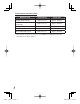
Guide number (GN) list TTL AUTO/AUTO ISO100, m ZOOM (mm) TTL AUTO/AUTO FOUR THIRDS With 135 Full emission 8 16 12 10 20 14 12 24 20 14 28 22 17 35 24 25 50 28 FOUR THIRDS 8 10 12 14 With 135 16 20 24 28 1/1 12.0 14.0 20.0 22.0 1/2 8.5 9.9 14.1 15.6 1/4 6.0 7.0 10.0 11.0 1/8 4.2 4.9 7.1 7.8 1/16 3.0 3.5 5.0 5.5 1/32 2.1 2.5 3.5 3.9 1/64 1.5 1.8 2.5 2.8 1/128 1.1 1.2 1.8 1.9 17 35 24.0 17.0 12.0 8.5 6.0 4.2 3.0 2.1 25 50 28.0 19.8 14.0 9.9 7.0 4.9 3.5 2.
FP MANUAL The following guide number figures have a 1/1 flash intensity ratio. ISO100, m ZOOM (mm) Shutter speed FOUR THIRDS With 135 1/125 1/160 1/200 1/250 1/320 1/400 1/500 1/640 1/800 1/1000 1/1250 1/1600 1/2000 1/2500 1/3200 1/4000 1/5000 1/6400 1/8000 8 16 8.5 7.5 6.7 6.0 5.3 4.7 4.2 3.8 3.4 3.0 2.7 2.4 2.1 1.9 1.7 1.5 1.3 1.2 1.1 10 20 9.9 8.8 7.8 7.0 6.2 5.5 4.9 4.4 3.9 3.5 3.1 2.8 2.5 2.2 2.0 1.8 1.6 1.4 1.2 12 24 14.1 12.5 11.2 10.0 8.8 7.9 7.1 6.3 5.6 5.0 4.5 4.0 3.5 3.2 2.8 2.5 2.2 2.0 1.
Light control range in AUTO mode Usable ISO sensitivity/aperture value (F) combinations for light control in AUTO mode AUTO light control range (m) ISO sensitivity 3200 1600 800 400 200 100 50 Aperture value F8 F5.6 F4 F2.8 F2 F1.4 Firing angle (mm) Upper row: FOUR THIRDS Lower row: 135 8 10 (W panel) (W panel) 12 14 17 25 35 42 20 16 (W panel) (W panel) 24 28 35 50 70 85 0.8 - 8.6 0.9 - 10.0 1.3 - 14.3 1.4 - 15.7 1.5 - 17.1 1.8 - 20.0 2.0 - 22.9 2.3 - 25.7 F11 F8 F5.6 F4 F2.8 F2 F1.4 0.
Continuous firing For your safety, be sure to observe the following. Continuous firings make the light-emitting section hot and may result in its deterioration, malfunction or deformation. Therefore, continuous firing should be limited to the counts shown in the following table. Always leave the electronic flash unused for at least 10 minutes after continuous firing up to the limit count. Limit counts of continuous firings Flash intensity Flash interval Limit count FULL; 1/1 6 sec. 10 1/2 3 sec.
Safety precautions (Be sure to read and observe the following) This instruction manual uses a variety of common symbols and icons to assist you in proper handling and usage of this product and to warn you of potential hazards to yourself and others as well as to property. These symbols and their significance are described below. This electronic flash has been designed exclusively for use with Olympus digital cameras.
WARNING Do not fire the flash or AF illuminator light immediately in front of a person’s eyes (particularly an infant). Exposure to the light from the flash at a very short range may cause irreparable injury to the eyes. Be especially careful to avoid using the electronic flash at a distance of less than 1 meter from an infant. Do not leave the electronic flash and batteries within reach of children. If a child swallows a battery or small accessory, see a doctor immediately.
CAUTION If you notice any abnormalities such as leakage, discoloration, deformation, overheating, or odor, stop using this device. Continued use could result in fire, overheating or explosion. Remove the batteries carefully to avoid burning yourself and to prevent exposure to gas or dangerous fluids that may be released. Contact your dealer or consult your Olympus Authorized Service Station. Always remove the batteries when you don’t expect to use the electronic flash for a long period.
BATTERY PRECAUTIONS Use only the specified batteries. Be sure to observe the following points. Otherwise, battery fluid leak, overheating, fire ignition and/or bursting may result. Do not mix old and new batteries, recharged and discharged batteries, batteries of different capacities, or batteries of different types or brands. Do not attempt to recharge non-rechargeable batteries such as alkaline batteries. Do not load or use the batteries with the +/– polarity reversed.
Caution for usage environment To protect the high-precision technology contained in this product, never leave the flash in the places listed below, no matter if in use or storage: • Places where temperatures and/or humidity are high or go through extreme changes. Direct sunlight, beaches, locked cars, or near other heat sources (stove, radiator, etc.) or humidifiers. • In sandy or dusty environments. • Near flammable items or explosives. • In wet places, such as bathrooms or in the rain.
For customers in USA FCC Notice This device complies with part 15 of the FCC rules. Operation is subject to the following two conditions: (1) This device may not cause harmful interference, and (2) this device must accept any interference received, including interference that may cause undesired operation. Any unauthorized changes or modifications to this equipment would void the user’s authority to operate. For customers in CANADA This Class B digital apparatus complies with Canadian ICES-003.
Specifications Model number Type Guide number : FS-FL36R : External electronic flash for digital still camera : Automatic switching 36: When in 42 mm (85 mm with the 135 type) 20: When in 12 mm (24 mm with the 135 type) 12/14 switching (when the wide panel is used) Firing angle : Automatic switching At 12 mm: Up/down 61°, Left/right 78° (equivalent to image angle of 12 mm lens)* At 42 mm: Up/down 21°, Left/right 28° (equivalent to image angle of 42 mm lens)* At 8 mm using the wide panel: Up/down 83°, Left/
RC function : Available when used together with cameras compatible with the Olympus wireless RC flash system. Effective distance : Up to approx. 10 m (32.9 ft.) Power supply : AA (R6) alkaline batteries, AA (R6) NiMH batteries, AA (R6) lithium batteries, AA (R6) oxyride batteries, AA (R6) NiCd batteries × 2 or CR-V3 lithium battery pack (Olympus LB-01) × 1 Dimensions : 67 (W) × 108 (H) × 95 (D) mm (2.6 × 4.3 × 3.7 in.) (excluding protrusions) Weight : 260 g (9.2 oz.
Printed in China r2067_e_000_cs2j.