INSTRUCTIONS INDUSTRIAL VIDEOSCOPE IPLEX MX II series
Contents Warning and Rating Plates............................................ 1 1. Rating plate A.......................................................................................... 1 2. Rating plate B.......................................................................................... 1 3. Warning plate .......................................................................................... 2 Important Information – Please Read Before Use....... 3 Intended use ...............................
3.2 Setting up the main unit ............................................................. 19 Using the handle ....................................................................................... 21 3.3 Preparing the power supply ...................................................... 22 Supplying power from the battery ............................................................. 22 Supplying power from the AC adapter ...................................................... 24 3.
4.2 Inserting the insertion tube ....................................................... 44 Holding the control unit and insertion tube................................................ 44 Inserting the insertion tube........................................................................ 45 Angulation operation ................................................................................. 46 4.3 Withdrawing the insertion tube .................................................
Chapter 6 6.1 Operations on a computer..................... 65 Using recorded images on a computer .................................... 65 Reading images with a computer.............................................................. 65 Chapter 7 Storage and maintenance...................... 66 7.1 Remaining battery power ........................................................... 66 7.2 Replacing the battery ................................................................. 67 Replacing the battery ..
Warning and Rating Plates Safety-related labels and symbols are attached to the instrument at the locations shown below. If labels or symbols are missing or illegible, please contact Olympus. 1. Rating plate A 3. Warning plate 2. Rating plate B 1. Rating plate A 2.
3.
Important Information – Please Read Before Use Intended use This instrument has been designed to be used with IPLEX MX II series and ancillary equipment for observation and examination of the insides of a machinery, equipment or building that cannot be observed directly from the outside. Do not use this instrument for any purpose other than its intended use, particularly for observation or examination of the inside of a human or animal body cavity.
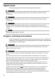
Signal words The following signal words are used throughout this manual. DANGER • Indicates an imminently hazardous situation which, if not avoided, will result in death or serious injury. WARNING • Indicates a potentially hazardous situation which, if not avoided, could result in death or serious injury. CAUTION • Indicates a potentially hazardous situation which, if not avoided, may result in minor or moderate injury. It may also be used to alert against unsafe practices or potential equipment damage.
• Do not allow the light emitted from the insertion tube’s distal end to enter your eye directly. Otherwise, an eye injury may result. • Should any abnormality be detected during angulation operation, do not continue the angulation operation by force. Otherwise, the insertion tube or examination target may be damaged. • Do not subject the LCD surface to impact or strong pressure. Doing so could shatter the LCD screen and cause personal injury. • Do not rub the LCD with hard or sharp objects.
• Do not remove the USB Flash Drive while playing back or recording still images. Otherwise, the data recorded in the USB Flash Drive may be destroyed. • Take care not to have your feet caught by a cord including the power cord or insertion tube. • Do not pull the cable of the insertion tube, control unit or other equipment with a strong force. Otherwise, the insertion tube or cable may be damaged or the instrument may topple down or drop.
Handling of the battery Follow the dangers, warnings and cautions described below when handling the battery. Otherwise, battery fluid leak, excessive heat generation, smoke, battery burst, electric shock and/or burns may result. DANGER • In case of Li-ion operation, be sure to use the battery and battery charger designated for IPLEX MX II series.
CAUTION • Do not soak the battery in or moisten it with water including rainwater and seawater. • Do not leave the battery in a place subject to moisture, water leak or extremely high or low temperatures. • Do not touch the battery terminals with a wet hand. • Be sure to recharge the battery before using them for the first time after purchase or after they have not been used for a long period. • When the battery is not to be used for a long period, be sure to remove them from the IPLEX MX II (main unit).
Product configurations of the IPLEX MX II series The IPLEX MX II series includes a main unit, control unit, and an insertion tube as shown in the table below. The simplified specifications of the insertion tubes are shown below. For detailed specifications of the individual models, see “Chapter 9 Specifications” (page 81). IPLEX MX II series model names IV8415M IV8430M IV8630M Max. insertion tube outer diameter φ 4.4 mm φ 6.0 mm Insertion tube length 1.
Chapter 1 Checking the package contents 1.1 Checking the package contents Match all items in the package with the components shown on “IPLEX MX II series package contents” below. If any item is damaged, a component is missing or you have any questions, do not use the instrument, but immediately contact Olympus.
Chapter 2 Instrument nomenclature and functions 2.
Chapter 2 Instrument nomenclature and functions Shoulder strap Insertion tube wrap belt 12
Chapter 2 Instrument nomenclature and functions 2.
Chapter 2 Instrument nomenclature and functions 2.
Chapter 2 Instrument nomenclature and functions Side view mirror adapter: 6-mm type (optional) Objective lens Mirror Product abbreviation (50S V7X2) Illumination Nut Side view mirror adapter lock groove NOTE • The insertion tube can temporarily be fixed on the control unit by inserting it into the insertion tube holder hole. • The insertion tube holder can be rotated or removed.
Chapter 3 Preparation and inspection before observation CAUTION • Be sure to finish the preparation and inspection work described below before use. If any irregularity is suspected, do not use the instrument but see “Chapter 8 Troubleshooting” (page 75) to solve the problem. If irregularity is still suspected, contact Olympus. Damage or irregularity may compromise the correct functioning of the instrument and may result in more severe damage to the examined subject.
Chapter 3 Preparation and inspection before observation Taking the instrument out of the case Remove the equipment in the order of: Main unit → Insertion tube → Control unit. Control unit Insertion tube Main unit Universal cable Remove the main unit. Remove the control unit and insertion tube. WARNING • Fully open the top cover when removing the main unit from the case. If the cover is not fully open, it can close unexpectedly and pinch your hand or cables.
Chapter 3 Preparation and inspection before observation CAUTION • Place the case on a level surface so it is stable. • To open the top cover of the case, release the latch on the front of the case. • Do not pull the insertion tube with excessive force when taking it out of the cushioned slot. Otherwise, the insertion tube may be damaged. • When taking the control unit or main unit out of the case, never hold them by the insertion tube or universal cable. It may damage the instrument.
Chapter 3 Preparation and inspection before observation 3.2 1 Setting up the main unit The main unit can be used in any one of the three setup configurations shown below.
Chapter 3 Preparation and inspection before observation CAUTION • Place the main unit on a level surface so it is stable. The main unit can tip over if it is not stable. • Do not place the main unit in overhead location. Doing so may result in the main unit falling and being damaged. • When suspending the base unit while using it, hook the handle someplace that can support its weight and where there is no danger of it falling.
Chapter 3 Preparation and inspection before observation Using the handle The handle can be lowered from its storage position and freely adjusted within the range shown in the illustration below. When using the handle as a stand, you can adjust the angle for easy viewing. CAUTION • Take care not to pinch your hand or other objects when moving the handle.
Chapter 3 Preparation and inspection before observation 3.3 Preparing the power supply WARNING • Do not bend, pull, twist, crush or apply excessive force to the power cord of the AC adapter. Otherwise, a break in the power cord wires may cause a fire or electric shock. • Ensure that the power cord is normal before connecting it. Using a power cord with irregularities may result in an electric shock. • Be careful not to injury yourself when replacing the battery.
Chapter 3 Preparation and inspection before observation 4 Insert the battery so that the ribbon passes under it. This is so you can pull the ribbon to remove the battery. Ribbon CAUTION • When loading the battery, check to make sure the main unit’s battery contacts and the battery terminals are positioned correctly. • Never try to force the battery if it does not slide in easily. Check to make sure that the battery is positioned correctly and that there is no problem with its terminals.
Chapter 3 Preparation and inspection before observation Supplying power from the AC adapter 1 2 Open the AC adapter connector cap. Connect the AC adapter to the AC adapter connector on the main unit. AC adapter connector cap 3 4 Ensure that the AC power cord is connected securely to the AC inlet of the AC power adapter. Plug the AC power cord securely into a power outlet. WARNING • Inspect the power cord before use and check for any signs of damage.
Chapter 3 Preparation and inspection before observation 3.4 Inspecting the insertion tube CAUTION • Be sure to hold the insertion tube by a position on the rear of the angulation section. Otherwise, the angulation section may be damaged. Inspecting the external appearance of the insertion tube 1 2 Check visually that the external finish of the complete length of the insertion tube and universal cable are free of irregularities such as deformation.
Chapter 3 Preparation and inspection before observation 3 4 Check that there is no dirt or water on the insertion tube distal end. If dust or water is present, wipe them clean with a soft piece of gauze or a cotton swab, grasping at hard part of distal end. The best results may be obtained using the lens cleaning fluid provided in the lens cleaning kit. Check that the distal end of the insertion tube is not deformed or loose.
Chapter 3 Preparation and inspection before observation 3.5 Inspecting the side view mirror adapter (optional) (for IV8630M) WARNING • The distal end of the insertion tube may become hot due to the illumination light or the internal heating caused by electrical parts. Do not forget to turn off the light source before attaching or detaching the side view mirror adapter. Touching the distal end immediately after having turned off light source may cause burn on your skin.
Chapter 3 Preparation and inspection before observation 2 Check the bores connection diameters of the side of the insertion tube distal end, side view mirror adapter lock groove and side view mirror adapter, and that their screws are not deformed or have foreign objects attached to them. Attaching and detaching the side view mirror adapter CAUTION • If the side view mirror adapter cannot be attached or detached because its nut will not turn, stop using the equipment and contact Olympus.
Chapter 3 Preparation and inspection before observation CAUTION • Do not use the side view mirror adapter with the green index. They cannot be attached correctly. • If the red index is not completely visible, you cannot insert the distal end of the insertion tube into or remove it from the side view mirror adapter. • The nut will fall off the mirror if it is loosened any further after the red index is completely visible (see below). If the nut comes off, it may be lost or the claws may be damaged.
Chapter 3 Preparation and inspection before observation 4 5 Lightly push the side view mirror adapter clockwise onto the insertion tube so that the second threaded section is engaged. Tighten the nut all the way until it is stopped. Make sure that the side view mirror adapter is securely attached. To detach the side view mirror adapter, reverse the attaching procedure. Inspecting the parts of the side view mirror adapter Check that the parts of the side view mirror adapter are not loosened.
Chapter 3 Preparation and inspection before observation 3.6 Inspecting the control unit and the universal cable 1 2 Check for irregularities such as damage or deformation to the external material, buttons, joysticks, and levers. Ensure that the universal cable is free of irregularities such as cuts and buckling.
Chapter 3 Preparation and inspection before observation 3.7 Inspecting the LCD monitor Inspecting the external appearance 1 Check that the LCD monitor is free of irregularities such as cracks on the screen. NOTE • The LCD panel is fabricated based on precision technologies. The LCD panel may contain pixels that do not light (visible as black dots) or light permanently (visible as bright dots), but this is not a defect or malfunction of the product.
Chapter 3 Preparation and inspection before observation 3.8 Mounting of the control unit on the main unit The control unit can be attached to the main unit as desired. It can be attached to the main unit for carrying and left attached to the main unit during observation. Handle Back attachment: For transport 1 Side attachment: For observation Insert the hanger on the side of the control unit straight into the control unit holder on the side or the back of the main unit.
Chapter 3 Preparation and inspection before observation 2 When attaching the control unit to the back of the main unit, check that it is positioned as shown in the figure below before attachment. Then, check that the control unit is firmly attached. Attaching it with excessive force in the wrong direction can cause the control unit to fall off and cause an accident. This also may damage the main unit.
Chapter 3 Preparation and inspection before observation CAUTION • Hold the handle of the main unit when transporting the main unit with the control unit affixed to the back. The main unit may fall or the excessive force to the main unit may damage connections if you lift it by the control unit. • Take care not to tilt or swing the main unit when carrying it with the control unit attached. Doing so can cause the control unit to fall off and cause unforeseen accidents or personal injury.
Chapter 3 Preparation and inspection before observation 3.9 Attaching and detaching the strap When you want to hang the IPLEX MX II (main unit) from your shoulder, attach the shoulder strap. Be careful not to use a shoulder strap other than those designated by Olympus and supplied with the IPLEX MX II unit. WARNING • Never attempt to carry an object other than the IPLEX MX II (main unit) using the shoulder strap. Otherwise, the strap may be damaged and cause the IPLEX MX II (main unit) to drop.
Chapter 3 Preparation and inspection before observation Two strap rings are provided for attaching the strap when transporting the main unit. Attach the strap to the two strap brackets and to one of the strap rings to do observations. During observation, attach the shoulder strap so that the side with the two connections is on the left side of the main unit, as shown in the figure below. The two connections can also be attached to the right side of the main unit.
Chapter 3 Preparation and inspection before observation 3 Use the length adjusters shown below to adjust the angle for easy viewing during observations. Length adjuster 4 Use the shoulder strap to hang the IPLEX MX II (main unit) from your shoulder.
Chapter 3 Preparation and inspection before observation 5 While walking with the control unit attached to the main unit (back, left side), insert the slack of the universal cable between the handle and the main unit. If the universal cable is dangling while you are walking, you may trip on it or have an accident. Universal cable 6 You can use the insertion tube wrap belt on the control unit to secure the insertion tube.
Chapter 4 Basic operations 4.1 Turning on the power Turning the power on 1 Hold down the main unit’s power button ( ) for at least two seconds and confirm that the power turns on. Power button ( ) Turning off the power Press and hold the power button ( ) on the main unit for 2 seconds. NOTE • The power turns off about 3 seconds after pressing the power button ( 40 ).
Chapter 4 Basic operations Checking the LCD monitor image 1 2 Ensure that the LCD monitor displays the observation image. Make sure there are no dark patches or dirt in the image. If you find any irregularities, go back to “3.4 Inspecting the insertion tube” (page 25) to check it again. NOTE • The screen displays and menu operations are enabled approximately 40 seconds after the power button ( ) is pressed.
Chapter 4 Basic operations Date and time settings Set the current date and time before using the system for the first time. For more information, see “Setting the date and time” (page 60). Checking the illumination lighting WARNING • The Illumination emitted from the insertion tube distal end may heat and ignite a nearby object. Be sure to set the illumination light turn off the LIGHT button ( ) on the front panel of the main unit when not using the instrument.
Chapter 4 Basic operations Checking the angulation lock 1 2 Pull the [ANGLE LOCK] lever up until it clicks. Confirm that angulation remains locked even when you remove your finger from the [ANGLE] joystick. Pull the [ANGLE LOCK] lever up until it clicks again to confirm the angle lock is released. Every time the [ANGLE LOCK] lever is pulled up and clicks, it changes from locked to unlocked and vise versa. CAUTION • Do not use the [ANGLE] joystick while the angle lock is on.
Chapter 4 Basic operations 4.2 Inserting the insertion tube Holding the control unit and insertion tube 1 2 3 44 In general, the [ANGLE] joystick of the control unit is manipulated with the thumb of the hand holding the grip of the control unit. Other buttons are also to be manipulated with the fingers of the hand holding the grip of the control unit. Hold the insertion tube with the other hand to which the control unit is being held.
Chapter 4 Basic operations Inserting the insertion tube While observing the monitor screen, carefully check the insertion direction as you slowly insert the insertion tube into the object being observed. Perform the angulation operation as required during insertion. Be careful not to apply excessive pushing force, twisting or tension to the insertion tube. WARNING • Be sure to turn the illumination light on during insertion into the object being examined.
Chapter 4 Basic operations Angulation operation 1 The insertion tube should be angulated as required for guidance or observation. See “Checking the angulation functions” (page 42) for details about angulation operation. NOTE • Increasing the insertion tube looping amount (bending amount) decreases the maximum angulation angle limit of the angulation section. Keep the insertion tube as straight as possible to get the best operation from the instrument.
Chapter 4 Basic operations 4.3 Withdrawing the insertion tube WARNING • The distal end of the insertion tube becomes hot just after use in high-temperature atmospheres. Do not touch it directly to avoid burns. CAUTION • Do not withdraw the insertion tube while its angulation is locked or while your finger is placed on the [ANGLE] joystick. Otherwise, the insertion tube and/or observation target may be damaged.
Chapter 4 Basic operations 4.4 Adjusting the image Still image (freeze) CAUTION • Do not insert and withdraw the insertion tube when the image is frozen. 1 Press the [FRZ/REC] button on the side of the control unit to freeze the observed image. The LCD monitor displays the freeze indicator ( ) on the top right of the screen. NOTE • If the [FRZ/REC] button is held depressed for more than 2 seconds, image recording will be initiated.
Chapter 4 Basic operations Adjusting the brightness While the live image is displayed, tilt the [BRT] lever on the control unit toward [S] to brighten the overall image or toward [T] to darken it. When the image brightness is adjusted, the LCD monitor displays the level indicator for about 3 seconds. Use the [BRT] lever when you want to change the overall brightness of the image.
Chapter 4 Basic operations 4.5 Recording the image Image recording preparation The USB Flash Drive should always be formatted on the main unit. See “Live screen/frozen screen menu display and functions” (page 57) for the operating procedure. CAUTION • If the USB Flash Drive is removed during image recording, the data in the recording media may be destroyed. Never attempt to remove the USB Flash Drive while recording images.
Chapter 4 Basic operations CAUTION • If the USB connector is wet, wait until it is thoroughly dry before connecting the USB Flash Drive. • If there is foreign matter inside the USB connector, remove all of it before connecting the USB Flash Drive. • Never connect any other USB device to the USB connector except for the USB Flash Drive provided as standard or USB Flash Drive recommended by Olympus.
Chapter 4 Basic operations 3 Note on the filenames a. A file named IV0?????.*** is created in the USB Flash Drive when an image is recorded. b. The “?????” indicates a 5 digit serial number in the file name “IV0?????”. The file number is a number between 00001 and 99999. When an image is recorded, the filename is assigned a file number one larger than the file with the largest file number already in the USB Flash Drive.
Chapter 4 Basic operations 4.6 Replaying the image Quick replay of most recent image Press the [VIEW/MENU] button in the live screen to display the most recently recorded image in full screen (the retrieve screen). Slide retrieval • During the retrieval of a still image, the retrieved image can be switched with the [BRT] lever or the [ZOOM] lever. • Use the [BRT] lever towards [S] or the [ZOOM] lever towards [T] to scroll images in order of their file names.
Chapter 4 Basic operations 4.7 Displaying a live image on an external monitor The video output connector of the main unit enables connection of a commercially available video cable with RCA pin plug for output of images to a monitor. Only live images can be output. Open the video connector cap to connect a video cable with RCA pin plug to the main unit. Video connector cap CAUTION • Recorded images cannot be output through the video output connector.
Chapter 5 Menu operations and functions Press the [VIEW/MENU] button on the control unit for at least 2 seconds (long push) opens a menu on screen, where various functions can be set and used. 5.1 Operating menu Menu operations 1 2 3 4 Press the [VIEW/MENU] button for at least 2 seconds (long push) to display the menu screen. Use the [BRT] lever or the [ZOOM] lever to select the menu to open. Press the [VIEW/MENU] button to execute the selected menu function.
Chapter 5 Menu operations and functions 2 Use the [BRT] lever or the [ZOOM] lever to select the [VIEW/MENU] button. , then press The “BEEP ON/OFF” window is displayed. 3 Use the [BRT] lever or the [ZOOM] lever to select “ON”, then press the [VIEW/MENU] button. Now the operation is complete. You can return to the menu screen and perform other menu settings. 4 To terminate the menu setting operation, select screen and press the [VIEW/MENU] button.
Chapter 5 Menu operations and functions 5.2 Using the live screen/frozen screen Live screen/frozen screen menu display and functions The menu on the live screen/frozen screen can be used for the following settings. Menu Description of function Initial status TITLE INPUT Title input operation. See “Inputting the title” (page 58) for details about operations. — WHITE BALANCE Sets the white balance characteristics of the system. Capture an image of a white object, such as a piece of paper.
Chapter 5 Menu operations and functions Inputting the title A title can be displayed in the live screen/frozen screen. The displayed title can be recorded together with the image. NOTE • You can input up to 30 characters for titles. • You can input the alphabet, Western European letters (with umlauts and other diacritic marks), numbers, and symbols. • If the language is set to Japanese, you can input single-byte katakana.
Chapter 5 Menu operations and functions Title input operations 1 Select an input mode. Use the [ZOOM] lever to select “A”, “1”, “#”, “À”, “ ”, or “ ” from the list of input modes on the right side of the screen, and then press the [VIEW/MENU] button. Use to input letters in the alphabet. Use to input numbers. Use to input symbols. Use to input special letters from European languages ((letters with umlauts, etc.) if the language is not set to Japanese).
Chapter 5 Menu operations and functions 4 Repeat steps 1 through 3 to complete inputting a title. If the title you are inputting is less than the maximum (30 letters), you can exit text input as follows. • Select “Space” and press the [VIEW/MENU] button continuously to input spaces to the end of the title field. • Select “ ” from the input mode on the right side of the screen and then select “ ” and press the [VIEW/MENU] button.
Chapter 5 Menu operations and functions 3 Use the [BRT] lever or the [ZOOM] lever to select numbers to set the “Year”, and then press the [VIEW/MENU] button. After “Year” is set, the input field changes to “Mon.”. Do the same operation to set “Mon.”, “Day”, “Hour”, and “Min.”. 4 5 6 To change the date format, select the minutes digits and then press the [VIEW/MENU] button to select “Year Mon. Day”. Use the [BRT] lever or the [ZOOM] lever to select a date format and then press the [VIEW/MENU] button.
Chapter 5 Menu operations and functions Language selection Sets the menu display language. You can select from available languages. 1 2 Press the [VIEW/MENU] button for at least 2 seconds (long push) to display the menu screen. Use the [BRT] lever or the [ZOOM] lever to select the [VIEW/MENU] button. , then press The “LANGUAGE” window is displayed. 3 Use the [BRT] lever or the [ZOOM] lever to select a language and press the [VIEW/MENU] button. The menu screen closes and “IN PROCESS” is displayed.
Chapter 5 Menu operations and functions 5.3 Using the retrieve screen Retrieve screen menu display and functions The menu displayed on the thumbnail/retrieve screen can be used for the following settings. Menu Description of function Initial status DELETE ALL All the images recorded in the “100IV7R1” folder on the USB Flash Drive are deleted. See “Delete image” (page 63) for details about operations. — DELETE Deleting images playing back in the retrieve screen.
Chapter 5 Menu operations and functions 2 Select and press the [VIEW/MENU] button. The “DELETE ALL” window is displayed. 3 Select “EXECUTE” and press the [VIEW/MENU] button to delete all images recorded in the “100IV7R1” folder on the USB Flash Drive. Deleting images playing back in the retrieve screen 1 2 Press the [VIEW/MENU] button for at least 2 seconds (long push) while a still image is displayed to display the menu screen. Select and press the [VIEW/MENU] button.
Chapter 6 Operations on a computer 6.1 Using recorded images on a computer You can use bundled IPLEX VIEWER PLUS to access images recorded with IPLEX MX II on a computer. Use a computer to read directly from the USB Flash Drive where the images you want to read are recorded. Reading images with a computer For details about how to open IPLEX MX II images with IPLEX VIEWER PLUS, see the IPLEX VIEWER PLUS instruction manual. CAUTION • Connect only USB Flash Drive to the main unit’s USB connector.
Chapter 7 Storage and maintenance 7.1 Remaining battery power When operating IPLEX MX II with the battery, the LCD monitor displays the remaining battery power on the top right of the screen. A guideline to remaining battery capacity is shown as follows. (1) Remaining battery power about 50%. (2) Remaining battery power about 25% to 50%. (3) Remaining battery power about 5% to 25%. (4) Remaining battery power about 2% to 5%. (5) Remaining battery power about 1% to 2%. This indicator flashes.
Chapter 7 Storage and maintenance 7.2 Replacing the battery DANGER • Before opening the battery cover, press the power button ( doing so may cause an electric shock. ) to turn off the power. Not WARNING • Be careful not to injure yourself when replacing the battery. • Never use a battery other than the one designated by Olympus. Otherwise, failure of the instrument may not only lead to a malfunction but also a fire.
Chapter 7 Storage and maintenance NOTE • If you are having trouble removing the battery, hook it with your finger to remove it. 4 68 See “Supplying power from the battery” (page 22) for information about putting in a new battery.
Chapter 7 Storage and maintenance 7.3 Cleaning Cleaning the insertion tube CAUTION • Clean the insertion tube immediately after withdrawing the insertion tube. If you leave it uncleaned, the equipment may be stained or corroded. • Do not use a hard cloth or hard brush for cleaning the insertion tube. Otherwise, the insertion tube may be damaged. 1 2 3 Use a clean, soft cloth to wipe any dirt or other foreign object off of the insertion tube.
Chapter 7 Storage and maintenance Cleaning the main unit and control unit If the main unit is dirty, wipe it with a soft cloth dampened with clean water. Then, lightly wipe it with a clean dry cloth. Also thoroughly wipe all dirt, water, and other foreign matter from the interior of the battery cover, video connector cap, AC adapter connector cap, and the locations where the insertion tube connects to the main unit. CAUTION • Do not clean the equipment under running water.
Chapter 7 Storage and maintenance 7.4 Repacking the case Repack the equipment in the order of: Control unit → Insertion tube → Main unit. Storage process label Control unit Insertion tube Stow the control unit first. Control unit Universal cable Insertion tube Main unit Storage groove Insertion tube Wind the insertion tube into the storage groove. Shoulder strap Stow the main unit on top of the insertion tube. Next, wind and stow the universal cable. Last, stow the shoulder strap.
Chapter 7 Storage and maintenance Stow accessories as illustrated below. Rigid sleeve (optional) Manual Utility disc AC power cord Lens cleaning kit AC adapter (2 pcs) • For main unit • For battery charger (optional) Battery (2 pcs/optional) Battery charger (optional) Rigid sleeve (grip/optional) USB Flash Drive Side view mirror adapter (optional) WARNING • Before storing the main unit in the case, be sure to remove the battery and turn the main unit off.
Chapter 7 Storage and maintenance Locking the case The top cover of the case may open if the case is hit while being moved. Use the provided key to lock the case during transport. CAUTION • Lock the case at both of the two locations.
Chapter 7 Storage and maintenance 7.5 Storage precautions Store the equipment under normal room temperature and humidity conditions. DANGER • Do not bend, stretch, twist or crush cables with excessive force. Otherwise, a break in a cable may result in a fire or electric shock hazard. CAUTION • Do not store the equipment in a place subject to high temperature, high humidity, excessive dust or fine particles, direct sunlight or radioactive emissions. Doing so could damage the equipment.
Chapter 8 Troubleshooting DANGER • Never use the instrument if there is any abnormality. Otherwise, the instrument may malfunction and the user may also be injured fatally, critically or seriously. Inspect the equipment as described in “Chapter 3 Preparation and inspection before observation”, do not use the equipment if there are any obvious malfunctions. Contact Olympus for repairs. Should the slightest irregularity be suspected, do not use the instrument and see “8.1 Troubleshooting guide” (page 76).
Chapter 8 Troubleshooting 8.1 Troubleshooting guide Error messages Problem Image cannot be recorded or retrieved. Display Possible cause Remedy NO RECORDING MEDIA. The USB Flash Drive is not inserted. Insert a USB Flash Drive to use and restart operation. RECORDING MEDIA FULL. The USB Flash Drive is full. Delete unneeded data to free up space or replace with new USB Flash Drive. THIS IMAGE CANNOT BE RETRIEVED. The image has not been recorded with the IPLEX MX II.
Chapter 8 Troubleshooting Problem Display Possible cause Remedy Self-check triggers during use and displays a message (and an alarm sounds). HIGH TEMPERATURE (MAIN UNIT). PLEASE TURN OFF THE POWER. The message prompts you to stop operations because the inside of the main unit was too hot and triggered the self-check function. Terminate inspection, allow the instrument to cool down, and then turn power back on again. The angulation operation is extremely heavy. OVER CURRENT (ARTICULATION MOTOR).
Chapter 8 Troubleshooting General troubles during operation Problem Possible cause The illumination does not light. The LIGHT button ( The LEDs on the distal end of the insertion tube are inoperable. Return the unit to Olympus for repair investigation. The illumination is dim. The distal end of the insertion tube is dirty. Wipe with a clean piece of gauze or a cotton swab. Extended use under high ambient temperatures causes decreased light emissions.
Chapter 8 Troubleshooting Problem The image is not sharp. Possible cause Remedy The object lens on the scope distal end is dirty. Wipe it with a clean piece of gauze or cotton swab. The side view mirror adapter is attached improperly. Attach the side view mirror adapter properly. The external monitor is adjusted incorrectly. Correctly adjust the external monitor. The automatic brightness control is set erroneously. Perform the [BRT] lever operation to configure the proper setting.
Chapter 8 Troubleshooting 8.2 Returning the instrument for repair WARNING • Olympus is not liable for any injury or damage which occurs as a result of repairs attempted by non-Olympus personnel. CAUTION • Olympus will not repair an instrument contaminated by noxious substances. Before returning the instrument for repair, contact Olympus. Include a detailed description of the malfunction and the conditions under which it occurs when returning the instrument.
Chapter 9 Specifications 9.1 Operating environment Operating temperatures Insertion tube In air : -25 to 80°C In water: 10 to 30°C Other parts than above In air Operating atmospheric pressure Insertion tube In air : 1013 hPa Under water: 1013 to 1317 hPa Other parts than above In air Operating environment humidity All parts 15 to 90% (Relative humidity) Liquid resistance Insertion tube No trouble when exposed to machine oil, light oil or 5% saline solution.
Chapter 9 Specifications 9.2 Other specifications Optical system Distal end Flexible section Total length 82 Field of view IV84 series: 100° IV86 series: 120° Direction of view Direct viewing Depth of field IV84 series: 12 to 50 mm (Fixed) IV86 series: 18 to 1000 mm (Fixed) Illumination LED illumination system Outer diameter IV84 series: φ 4.4 mm IV86 series: φ 6.0 mm Distal end rigid section length IV84 series: 14.85 mm IV86 series: 21.
Chapter 9 Specifications Control unit Angulation Power assisted angulation. Function of buttons ZOOM (T/W) lever 3-step zoom magnification switching Switches the retrieved image. Used for menu selections. BRT (S/T) lever Brightness changes in UP/DOWN format. Switches the retrieved image. Used for menu selections. ANGLE joystick Used to control the angulation.
Chapter 9 Specifications Setup configuration Three setup configurations are supported. • Using the handle as a stand for the main unit • Suspending the main unit from the handle • Mounting the main unit on a tripod Portability Can be fitted to body with a shoulder strap. Holding of control unit Provided with a hook for locking of the control unit. LCD panel TFT full color liquid crystal display panel module. Transparent panel 6.
Chapter 9 Specifications Power supply Battery Specified battery can be inserted and removed from the battery slot. Only the specified battery is permitted: Specified battery (Lithium Ion) Model name: Manufactured by INSPIRED ENERGY NC2040OL24 Nominal voltage: 10.8 V Battery powered operating time: 120 minutes or longer (based on a new battery) For details, refer to the instruction manual of your battery. AC adapter Designated AC adapter can be connected to AC adapter connector.
Chapter 9 Specifications Beep tone setting Beep tone output can be turned on or off by menu operation. Carrying case specifications Equipment stored in carrying case Dimensions weight 86 Insertion tube, Control unit, Main unit Stowed in storage space. Other items • • • • • • • • • • • Dimensions 600 (W) x 133 (D) x 426.5 (H) mm 23.62 (W) x 5.16 (D) x 16.79 (H) inch Weight Approximately 3.0 kg (7.
Chapter 9 Specifications Side view mirror adapter specifications The following specifications represent the performance of the side view mirror adapter (optional) when it is attached to the insertion tube. The side view mirror adapter can be attached to the IV8630M. AT50S-IV76X2 Adapter model name 50S V7X2 Field of view *1 50° Direction of view *2 Side Optical system Depth of field *3 Distal end External view 5 to 1000 mm Outer diameter *4 φ 7.4 mm Distal end rigid section length *5 35.
Chapter 9 Specifications External application standard Low Voltage Directive and EMC Directive This device complies with the requirements of Directive 2006/95/EC concerning electrical equipment designed for use within certain voltage limits. This device complies with the requirements of Directive 2004/108/EC concerning electromagnetic compatibility when used in combination with devices bearing CE marking either on the products or in its instructions.
Chapter 9 Specifications 89
Appendix System chart Insertion tube wrap belt Shoulder strap External monitor (NTSC/PAL) (commercially available) Video cable with RCA pin plug (commercially available) Main unit 4.
Side view rigid sleeve (optional) MAJ-1731 MAJ 1731 MADE IN JAPAN IPLEX VIEWER PLUS 4.4-mm type • MAJ-1730 6-mm type • MAJ-1731 USB Flash Drive Rigid sleeve (optional) 4.
92
Shinjuku Monolith, 3-1 Nishi-Shinjuku 2-chome, Shinjuku-ku, Tokyo 163-0914, Japan Telephone: (81)3-6901-4038 Wendenstrasse 14-18, 20097 Hamburg, Germany Telephone: (49)40-23-77-30 48 Woerd Ave Waltham, MA 02453, U.S.A. Telephone: (1)781-419-3900 KeyMed House, Stock Road, Southend-on-Sea, Essex SS2 5QH, U.K. Telephone: (44)0-1702 616333 491B, River Valley Road #12-01/04, Valley Point Office Tower, Singapore 248373 Telephone: (65)6834-0010 House 27, Bld.