® User’s Guide Shop online at omega.com ® e-mail: info@omega.com For latest product manuals: omegamanual.
® OMEGAnet ® Online Service omega.com Internet e-mail info@omega.com Servicing North America: U.S.A.: ISO 9001 Certified Canada: Omega Engineering, Inc., One Omega Drive, P.O. Box 4047 Stamford, CT 06907-0047 USA Toll Free: 1-800-826-6342 TEL: (203) 359-1660 FAX: (203) 359-7700 e-mail: info@omega.com 976 Bergar Laval (Quebec), H7L 5A1 Canada Toll-Free: 1-800-826-6342 FAX: (514) 856-6886 TEL: (514) 856-6928 e-mail: info@omega.ca For immediate technical or application assistance: U.S.A.
OM-DAQ-USB-2400 Multiple Channel USB Data Acquisition Module TABLE OF CONTENTS Page Section 1 - Introduction ....................................................................... 1-1 1.1 Precautions ................................................................................................ 1-1 1.2 Safety Warnings and IEC Symbols ......................................................... 1-2 1.3 Statement on CE Marking ........................................................................ 1-2 1.
TABLE OF CONTENTS OM-DAQ-USB-2400 Multiple Channel USB Data Acquisition Module Page 5.4 Triggering ................................................................................................... 5-4 5.5 Signal Modes ............................................................................................. 5-4 5.6 System Noise ............................................................................................. 5-6 5.7 Averaging ...............................................................
OM-DAQ-USB-2400 Multiple Channel USB Data Acquisition Module LIST OF FIGURES List of Figures Section Section 1 Figure 1-1 1-2 Description .............................................................. Page IEC Symbols ............................................................... 1-2 System Components ................................................. 1-3 Section 3 3-1 3-2 3-8 OM-DAQ-USB-2401 Hardware and Dimensions ... 3-1 Connection of an OM-DAQ-USB-2401 System to a Computer USB Port .............
LIST OF FIGURES OM-DAQ-USB-2400 Multiple Channel USB Data Acquisition Module List of Figures Section 4-27 4-28 Description ............................................................. Page OM-DAQ-USB-2400 Block Diagram .................... 4-14 OM-DAQ-USB-2401 Single-ended and Differential Conections to Analog Input Channels Diagram ... 4-16 Calibration/Scan Arrangement ............................ 4-17 Thermocouple Wiring ............................................
Introduction 1 Section 1 - Introduction Please read this manual completely before installing and operating your Omega data acquisition system. It’s important to read and follow all notes, cautions, warnings and safety precautions before operating this device. “Device” refers to your data acquisition unit. 1.1 Precautions • This device is not designed for use in any medical or nuclear applications. • Do not operate this device in flammable or explosive environments.
1 Introduction NOTE: When using OM-DAQ-USB-2401 unit to acquire data, computer energy save modes can cause false data readings. Prior to using the unit, ensure your computer’s energy save mode is disabled. If needed, consult your PC user’s manual to disable energy save (power suspension) modes. 1.2 Safety Warnings and IEC Symbols This device is marked with international safety and hazard symbols in accordance with IEC standards.
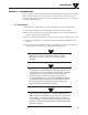
Introduction 1 NOTE: *At highest scan rate, 1000 samples/sec +/- 1% with one channel on, +/- 5% with all channels on. The main items you will be using in your data acquisition system are the OM-DAQ-USB-2401 unit, its USB cable, and power adaptor. POWER ADAPTER (OPTIONAL) OM-DAQ-USB-2401 MODULE USB PC WITH USB CONNECTION (NOT INCLUDED) Figure 1-2.
2 Hardware Section 2 - Hardware It is important that you read this manual completely and follow all safety precautions before operating this instrument. 2.1 Package Inspection Remove the packing list and verify that you have received all your equipment. If you have any questions about the shipment, please call our Customer Service Department at 1-800-622-2378 or 203-359-1660. We can also be reached on the Internet at omega.com, e-mail: cservice@omega.com.
Hardware Setup 3 Section 3 - Hardware Setup 3.1 OM-DAQ-USB-2401 System Components 127 (5.00) A A C A A C E C 5 5 O 6 6 O X O H L M H L M C M ANALOG INPUT 12 V OUT CHANNEL 5 & 6 97 (3.80) A A C A A C E C 7 7 O 8 8 O X O H L M H L M C M ! ANALOG INPUT 12 V OUT CHANNEL 7 & 8 OM-DAQ-USB-2400 SERIES USB DATA ACQUISITION SYSTEM CHANNEL 1 & 2 ANALOG INPUT ! 12 V OUT A A C A A C E C 1 1 O 2 2 O X O H L M H L M C M 107 (4.
3 Hardware Setup 3.2.1 USB-powered Hubs These hubs draw all power from the host USB connector’s power pins. The power is used for hub internal functions and for the hub’s ports. Each port of a USB-powered hub must be capable of supplying at least 100 mA. 3.2.2 Self-powered Hubs These hubs draw power from a source other than the host USB connector, with exception that they may draw up to 100 mA from their upstream connection for hub internal functions.
Hardware Setup 3 3.3 Connecting Your OM-DAQ-USB-2401 Acquisition System to PC NOTE: When using a power adaptor with your DAQ system, be sure to supply power (from the adaptor to the DAQ) before connecting the USB cable. This allows your DAQ to inform the host computer (upon connection of the USB cable) that the unit requires minimal power from the computer. Use an approved high-speed USB cable to connect the DAQ system to one of the host computer’s USB ports.
3 Hardware Setup 3.4 Connecting Various Hardware Setups ON-DAQ-USB-2401 data acquisition systems range from simple to complex. One example of a simple system is that of one OM-DAQ-USB-2401 connected to a PC’s USB connector. A much more complex system is one that contains 10 OMDAQ-USB-2401 units and a combination of USB-powered and self-powered hubs. Despite the wide range of possibilities in between, use of the following examples should enable you to properly connect your system.
Hardware Setup 3 3.4.2 Connection to USB-powered Hub In this example, two OM-DAQ-USB-2401s are connected by cable to individual ports of a single USB-powered hub. Since the hub receives all its power from the computer’s USB, the hub cannot supply adequate power to the DAQ units. Because of this aspect of insufficient power, each unit is connected to its own power adaptor. POWER ADAPTER POWER ADAPTER USB HUB USB Figure 3-4.
3 Hardware Setup POWER ADAPTER POWER ADAPTER USB HUB USB POWER ADAPTER USB HUB Figure 3-5. Connections to Self-Powered Hub and to USB-Powered Hub NOTE: USB port locations vary from PC to PC. 3.
Hardware Setup 3 3.5.1 OM-DAQ-USB-2401 Wall Mounting In order to mount the OM-DAQ-USB-2401 to the wall, you will need to: 1. Remove the rear screws from the OM-DAQ-USB-2401. 2. Align the mounting brackets with the rear holes on the DAQ unit (make sure that the ears are facing outwards, like in the figure below). 3. Use the longer screws to reconnect the mounting brackets to the body of the enclosure, in the same direction as the screws that were removed from the DAQ unit. 4.
3 Hardware Setup 3.5.2 OM-DAQ-USB-2401 DIN Rail Mounting In order to mount the OM-DAQ-USB-2401 to a DIN-Rail, you will need to: 1. Attach the DIN-rail plastic adaptors to the mounting brackets, using the four shorter screws. 2. Remove the rear screws from the OM-DAQ-USB-2401. 3. Align the mounting brackets with the rear holes on the DAQ unit (make sure that the ears are facing inwards, like in the figure below). 4.
Software 4 Section 4 - Software 4.1 Getting Started The following program files are included on the Omega DAQ Central User Software CD supplied with your data acquisition unit. These files can also be downloaded from the omega.com website should you misplace your CD. • DAQ Central data logging software installer • Omega.DAQ .NET API NOTE: When using Omega DAQ modules to acquire data, computer energy save modes can cause false data readings.
4 Software 4.2.2 Software Setup Insert the DAQ Central Software CD that was included with your DAQ unit into the CD-ROM drive on your PC. Your system should begin the installation process automatically. If the software installation does not start automatically: open: "My Computer", double-click your CD-ROM drive, and run "setup.exe". Figure 4-1. Welcome Screen This welcome screen should be visible on your computer screen. To continue with installing the program click the “Next >” button.
Software 4 Figure 4-3. Confirm Installation Screen The setup wizard now has all the information to complete the installation of the software on your PC. To continue with installing the program click the “Next >” button. During the install process, a Windows Command Prompt may pop up. No interaction is required in this window; it is automatically installing or updating the device’s USB drivers. Please let this process complete before closing the software installation wizard.
4 Software 4.3 DAQ Central Software Operation Below is the basic flow of operation when using the software: 1. Highlight desired device. 2. Open Device Configuration window. 3. Set channels, sample rate, triggering, and data output file. 4. Click “OK” to confirm Device Configuration. 5. Open any desired Data Displays. 6. Click the Start button. Details on the various windows and options can be found in the rest of this chapter. Figure 4-4.
Software 4 TOOLBAR BUTTONS Start Button Initiates data acquisition for the highlighted device. Even if a Start Trigger is set, this must be pressed to Arm the device. Stop Button Stops data acquisition for the highlighted device. If a Stop Trigger is set, this will cancel the trigger. Device Configuration Icon Accesses the Device Configuration window for the selected device.
4 Software 4.3.1 Main Control Window Pull-Down Operations Below are the operations that are available in the Pull-Down Menus of the DAQ Central Main Control Window. Figure 4-5. File Menu Open Configuration Opens Device Configuration settings from a saved file Save Configuration As Saves current Device Configuration settings to a new file name These settings files contain all of the data that is found in the Device Configuration window. Figure 4-6.
Software 4 Figure 4-7. Tools Menu Export Data File – To convert data file from binary file to .csv file Fgure 4-8. Help Menu Check for Updates To check for the latest Omega DAQ Central software update information through the Internet connection. About To view software version.
4 Software Section 4.3.2 Device Configuration The Device Configuration window contains the Channel, Triggers, and Data tabs. Details for these tabs are below. When finished making changes, press “OK” to confirm the changes or “Cancel” to abandon the changes. Figure 4-9. Configuration Mode - Channels Tab Screen Channels Tab The Channels tab contains a spreadsheet designed for setting up channels for data acquisition.
Software 4 Configuration Parameter Settings Channel The input channel’s name (not editable) AN1D = analog channel 1, differential input AN1H = analog channel 1, single-ended high input AN1L = analog channel 1, single-ended low input Etc. Nickname You can specify the Nickname (e.g., Oven 1, Monitor Room) Units You can specify the Engineering Unit. When switching between voltage and thermocouple ranges, this will automatically switch to the default units for that range.
4 Software Figure 4-13. Trigger Options The Triggers tab is used to set up triggers for starting and stopping data acquisition. The Start Trigger and the Stop Trigger each have a different set of available trigger types: Figure 4-14. "Start Trigger" Options Figure 4-15. "Stop Trigger" Options Trigger Types Manual Acquisition is manually started/stopped. Level Set trigger to stop/start acquistition when the input level is either above or below a certain threshold.
Software 4 NOTE: For all Start Trigger types, the device must be armed by pushing the Start Button on the main window. Data storage and display will not begin until the device triggers. Data Tab Figure 4-16. Data Tab To save data to a file on the PC, select the Data tab and choose a filename. This data can be saved in Binary or Delimited (.csv) format. • Binary format is faster, and is recommended for slower PCs. Binary format also creates files that are about 50% smaller than Delimited files.
4 Software Figure 4-18. Main Window Screen Figure 4-19. Gauges Screen Figure 4-21. Digital Screen 4-12 Figure 4-20. Bars Screen Figure 4-22.
Software 4 Figure 4-23. Waveform Screen Each Data Display can be customized by clicking the Options Icon . Each Data Display's Options screen lets you choose which device channels to display in that window. Channels can be added or removed with the Add Display and Delete Display buttons. Confirm changes by clicking the OK button. Start Acquistion by clicking the Play button on the Main Window. Acquistion can be stopped with the Stop button. Figure 4-24.
4 Software 4.4 Power Line Rejection The OM-DAQ-USB-2401 Series can take readings while making use of 50/60Hz line cycle rejection. While in the line cycle rejection mode, the maximum sample rate is as follows: • 50 Hz rejection: Scan Rate (SR) Range: 0.153Hz < SR <= 1Hz • 60 Hz rejection: Scan Rate (SR) Range: 1Hz < SR <= 1.
Software 4 The converter is comprised of a 4th-order, delta-sigma (Δ∑) analog-to-digital (A/D) converter modulator followed by a programmable digital filter. A flexible input multiplexer handles differential or single-ended signals; the programmable filter allows the user to optimize between a resolution of up to 23 bits noise-free. Examples of scan sequences, with various channel resolutions and calibration arrangements, appear in Table 5-1 on page 5-2. 4.
4 Software NOTE: In DAQ applications, thermocouples should not be connected single-ended. Doing so can result in noise and false readings. This is especially true when acquiring other high-amplitude signals in conjunction with thermocouple signals that are connected single-ended. The DAQ units include built-in cold-junction compensation (CJC), which is automatically invoked when you select TC measurements.
Software 4 Resolution (Effective Number of Bits - ENOB, RMS) – The number of reliable data bits that exist for a signal’s measurement. The greater the resolution, the more detailed the reading. For example, with an increased resolution, a reading of 5.12 V could become 5.11896 V. The DAQ actually provides for 24 bits of data information; however, the accuracy of the least significant bits decreases as the measurement duration speeds up.
4 Software 4.11 Thermocouple Measurements The OM-DAQ-USB-2401 provides effortless thermocouple (TC) measurements. The unit includes built-in cold-junction compensation (CJC), which is automatically invoked when you select TC measurements. The DAQ unit automatically converts acquired voltage readings into compensated-linearized temperature readings. A DAQ system can make thermocouple and volts measurements concurrently.
Signal Management 5 Section 5 – Signal Management 5.1 Channel Control and Expansion In the OM-DAQ-USB-2401 system, the quantities and types of DAQ units used determine the system’s channel capacity. Up to 10 OM-DAQ-USB-2401s can be used with one host PC. See the Specifications for more detailed channel information. 5.2 Scan Time and Resolution 5.2.1 Scan Time Scan Time (per scan) - The amount of time used for scanning (sampling) all selected channels’ input signal.
5 Signal Management Scan Rate vs. Resolution2 Scan Rate (Scans per Second - SPS) 3,4 Speed Designation Very Slow, 50 / 60 Hz rejection Scan Time1 (s) Resolution (ENOB5 RMS) 3600s>=ST >= 6.5s 0.0002778=< SR <= 0.153 22.5 Slow, 50 Hz rejection 6.5s> ST >= 1s 0.153 < SR <=1 21 Slow, 60 Hz rejection 1s> ST >=0.6s 1 < SR <= 1.67 20.9 Medium, 60 Hz rejection 0.6s> ST >=0.3s 1.67 < SR <= 3.33 20.4 Medium, 50 Hz rejection 0.3s> ST >=0.2s 3.33 < SR <= 5 20.3 0.2s> ST >=0.
Signal Management 5 The following table provides general advice regarding the selection of Scan Time. The concepts are further illustrated by the figure, Examples of Under Sampling. Analog Input Signal Scan Time (Measurement Duration) Scan Rate (Sample Rate) Resolution Steady, or gradual change Long Low High Highly variable (unsteady) Short High Low Figure 5-1. Examples of Under Sampling The above figure depicts three signals from the same temperature fluctuations.
5 Signal Management 5.4 Triggering Triggering controls an acquisition cycle. Once the system is armed, a trigger is required to collect the data. The user must determine the triggering requirement based on the nature of the measurement and the amount of data needed to satisfy the system’s purpose. The trigger source can be a software command or an analog input channel on reaching a specified voltage level can be used to trigger the system.
Signal Management 5 Differential mode refers to a mode, or circuit set-up, in which a voltage is measured between two signal lines. The measured differential voltage is used for a single channel. An advantage of using differential inputs is that they reduce signal errors and the induction of noise resulting from ground current. The following illustration is an example of how noise is reduced, or canceled-out, when using the differential Figure 5-3.
5 Signal Management Resolution: An analog-to-digital converter (ADC) converts an analog voltage to a digital number. The digital number represents the input voltage in discrete steps with finite resolution. ADC resolution is determined by the number of bits that represent the digital number. An n-bit ADC has a resolution of 1 part in 2n. Thus, 12 and 16 bit resolutions are as follows: • 12-bit resolution: 1 part in 4096 (212), corresponding to 2.44 mV in a 10 V range.
Signal Management 5 5.9 Input and Source Impedance As illustrated below, the input impedance (Ri) of an analog-to-digital converter combines with the transducer’s source impedance (Rs) forming a voltage divider. This divider distorts the voltage being read at the analog-to-digital converter. The actual voltage read is represented by the equation: VADC = VT x Ri / (Rs + Ri) The input impedance (Ri) of most ADCs is at least 1 MΩ; low source impedance (Rs) usually presents no problem.
6 CE Conformity Section 6 - CE Conformity 6.1 OM-DAQ-USB-2401 Design for CE Conformity The OM-DAQ-USB-2401 has been designed to meet requirements as outlined in European Community EMC Directive EN61326. Three ferrite cores are included in the OM-DAQ-USB-2401 package. When powering the unit using the adapter, the ferrite cores must be attached to both the USB cable and the power adapter to meet EFT (Electrical Fast Transient) specifications. Refer to Figure 6-1.
CE Conformity 6 UNSNAP FERRITE CORES HERE Figure 6-2 Ferrite Core The ferrite cores may be removed from the DAQ unit; however, in order to conform to CE standards, all of the ferrite cores must be attached to the USB cable and power adapter. NOTE: If the user is not using the power adapter but relying on power from the host USB connection, no ferrites are required.
7 Troubleshooting Section 7 – Troubleshooting 7.1 Basic Checklist Power – Check USB cable connection. The green “PWR IND” LED should be lit on the DAQ device. If using a powered USB hub, make sure its power cable is plugged in. Signal – Check signal lines and connections. Connectors must be free of corrosion. Signal lines should be undamaged and free of sharp bends and twists. Signal paths should avoid potential sources of noise (high voltage and electromagnetic interference).
Service and Calibration 8 Section 8 – Service & Calibration Your Omega DAQ components have been built and factory calibrated to meet or exceed the specifications listed here in this manual. The following section provides information on how to have your device serviced. 8.1 Service & Calibration If any of your DAQ system components require service or calibration, please call our Customer Service Department at 1-800-622-2378 or 203-359-1660.
9 Specifications Section 9 – Specifications 9-1 General Isolation: 500V from PC External Excitation Output Voltage: +12v DC Regulated, Maximum total current output 67mA Power Requirements: Powered from USB port max 500 mA, or from external 7.5 to 12 Vdc, (1.0 A recommended) Thermocouple Types: J, K, T, E, R, S, B, N Cold-Junction Compensation Accuracy: Isolation: ±1.
Specifications Thermocouple Input Range: Cold Junction Compensation Accuracy: Input Voltage Range Relative To Analog Common (COM): Input Resistance: 9 Type J: -18 to 1200°C (0 to 2192°F) Type K: -129 to 1372°C (-200 to 2502°F) Type T: -101 to 400°C (-150 to 752°F) Type E: -184 to 1000°C (-300 to 1832°F) Type R: 204 to 1768°C (400 to 3214°F) Type S: 204 to 1768°C (400 to 3214°F) Type B: 538 to 1820°C (1000 to 3308°F) Type N: -129 to 1300°C (-200 to 2372°F) ±1.
9 Specifications Table 9-1. Thermocouple Accuracy (ºC) for OM-DAQ-USB-2401 TC Type Temp. (°C) Typical Slow Fast J -18 0 1200 1.3 1.1 0.9 3.8 3 2.5 K -129 0 1372 1.8 1.4 1.3 5 3.9 3.7 T -101 0 400 1.6 1.4 1 4.5 4 2.9 E -184 0 1000 1.2 0.9 0.7 3.4 2.6 1.9 R 204 700 1768 5.2 4.6 3.9 14.8 13.1 11 S 204 700 1768 5.6 5.2 4.6 16 14.7 12.8 538 1820 7.9 4.8 13.7 13.7 -129 0 1300 2.6 2 1.4 7.3 5.9 4 B N NOTE: Thermocouple accuracy excludes cold junction compensation error.
Approvals and Regulatory Compliance 10 10.1 International Usage & CE Marking The OM-DAQ-USB-2401 multiple channel USB data acquisition module is CE marked and certified for use in several European countries. Please contact OMEGA for information on International Regulatory Compliance for each country. It is your (the user’s) responsibility to insure that these products are operated within the guidelines here in this manual and in conformance with all local or national regulations and laws.
NOTES: 10-2
NOTES: 10-3
NOTES: 10-4
WARRANTY/DISCLAIMER OMEGA ENGINEERING, INC. warrants this unit to be free of defects in materials and workmanship for a period of 13 months from date of purchase. OMEGA’s WARRANTY adds an additional one (1) month grace period to the normal one (1) year product warranty to cover handling and shipping time. This ensures that OMEGA’s customers receive maximum coverage on each product. If the unit malfunctions, it must be returned to the factory for evaluation.
Where Do I Find Everything I Need for Process Measurement and Control? OMEGA…Of Course! Shop online at omega.