OMEGAnet On-Line Service SM http://www.omega.com Internet e-mail info@omega.com Servicing North America: USA: ISO 9001 Certified Canada: One Omega Drive, P.O. Box 4047 Stamford, CT 06907-0047 TEL: (203) 359-1660 e-mail: info@omega.com 976 Bergar Laval (Quebec) H7L 5A1 TEL: (514) 856-6928 e-mail: info@omega.
CONTENTS 1. 2. 3. 4. 5. 6. 7. 8. 9. General Information and Features Applicable Standards Installation and Removal Input and Output Connections Specifications 5.1 PS Type Labeling 5.2 Size & Weight 5.3 Mounting 5.4 Temperature Ranges 5.5 Input Range 5.6 Input Current Surge Protection 5.7 Output Voltage 5.8 Output Current 5.9 Output Ripple 5.10 Temperature Derating 5.11 Power-on Indicator 5.12 Short-circuit and overload protection 5.
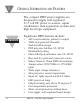
1 GENERAL INFORMATION AND FEATURES The compact DRN power supplies are designed to supply well-regulated 21.5 volt DC power to sensors, signal conditioners, data acquisition systems and high level logic equipment.
APPLICABLE STANDARDS 2 2.1 Input Voltage Tolerances Exceeds IEC 38 range 2.2 Input / Output Isolation 4KV rms 60Hz 1 minute test 630V conductor spacing, IEC 348 Exceeds VDE551 / IEC 742 separation spacing Exceeds VDE106 protective separation Exceeds VDE 160 clearance distances Exceeds VDE160 creepage distances 2.3 Protective Classes IEC 529: IPÐ20 VDE 106 Part 1: Class II 2.
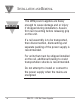
3 INSTALLATION AND REMOVAL Warning! The DRN power supplies are heavy enough to cause damage and or injury if dropped during installation. Assure firm rail mounting before releasing grip on the unit. If a rail assembly is to be transported, then disconnection, dismounting and separate packing of the power supply is recommended. For units that must be shipped installed on the rail, additional bracing to resist transportation shocks is recommended.
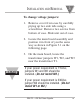
INSTALLATION AND REMOVAL 3 To change voltage jumpers: 1. Remove cover from case by carefully prying up two side tabs using a screwdriver. Remove two screws from bottom of case. Slide unit out of case. 2. Locate the main board assembly and position it in front of you the same way as shown in Figure 3.1 on the following page. 3. On the main board, locate the transformer jumpers W1, W2, and W3 near the transformer T1. Warning! If your power requirement is 115Vac, jumpers W1 and W2 should be installed.
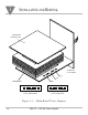
3 INSTALLATION AND REMOVAL TRANSFORMER MOUNTING PLATE T1 SHOWN WITH 115VAC WIRING W1 W3 MAIN BOARD W2 W2 W3 W1 230VAC JUMPER WIRING W2 W3 W1 115VAC JUMPER WIRING Figure 3.
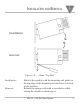
INSTALLATION AND REMOVAL 3 installation removal Figure 3.2 Ñ 35mm "Top Hat" Installation: Removal: Hook in the module with the mounting rail guide on the top edge of the mounting rail and lower it to lock it into position. Release the spring catch with a screwdriver while raising the module to disengage it.
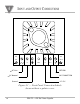
4 INPUT AND OUTPUT CONNECTIONS AC DC IN OUT N PWR +V N/C RETURN AC Line AC Neutral NO CONNECTION Ground +21.5V Figure 4.
SPECIFICATIONS 5 5.1 PS Type Labeling DRNÐPSÐ750, where 750 equals mA rating. DRNÐPSÐ750 5.2 Size & Weight Height: Width: Depth: Weight: 2.76" 2.95" 5.95" 2.0 lbs. (70mm) (75mm) (151mm) (0.9 kg) 5.3 Mounting 35mm "top hat" DIN EN 50022 5.
5 SPECIFICATIONS 5.5 Input Range 115 or 230V, 49Ð61Hz DRNÐPSÐ750 ± 10% 5.6 Input Current Surge Protection 6kA/275V Varistor 5.7 Output Voltage 21.5V ± 2% - IR, where I = output current amperes and R = 0.3½ 5.8 Output Current DRNÐPSÐ750 0Ð750mA 5.
SPECIFICATIONS 5 5.10 Temperature Derating None below 50 degrees C DRNÐPSÐ750, 15mA per degree C above 50¡C 5.11 Power-on Indicator Front Panel red LED lamp 5.12 Short-circuit and overload protection DRNÐPSÐ750 foldback current limiting with automatic high temperature shutdown no fuses required 5.13 Wire Connections Screw down wire clamps, AWG 12 to 26 (ferrules recommended for stranded wire).
DERATING GRAPH / BLOCK DIAGRAM 6/7 1000 800 DRN-PS-750 75mA 600 I max. 400 200 0 -5 5 15 25 35 45 60 50 ¡C Ambient Figure 6.1 Ñ Derating Graph AC Line INPUT: 115/230vac 49-61Hz AC Neutral V A R I S T O R L C F I L T E R (+V) B R I D G E R E G U L A T O R 21.5V ( ) Return Ground Figure 7.
DIMENSIONS DRAWING 8 FASTEN RAIL UNDER POWER SUPPLY WITH TWO SCREWS SPACED AS SHOWN. 3.15 [80.0] 2.95 [75.0] 2.76 [70.0] 5.95 [151.1] MAX Figure 8.
SAFETY CONSIDERATIONS This device is marked with the international Caution symbol. It is important to read this manual before installing or commissioning this device as it contains important information relating to Safety and EMC (Electromagnetic Compatibility). Unpacking & Inspection Unpack the instrument and inspect for obvious shipping damage. Do not attempt to operate Note ☞ the unit if damage is found.
MADE IN USA WARRANTY/DISCLAIMER OMEGA ENGINEERING, INC. warrants this unit to be free of defects in materials and workmanship for a period of 13 months from date of purchase. OMEGA Warranty adds an additional one (1) month grace period to the normal one (1) year product warranty to cover handling and shipping time. This ensures that OMEGAÕs customers receive maximum coverage on each product. If the unit should malfunction, it must be returned to the factory for evaluation.
Where Do I Find Everything I Need for Process Measurement and Control? OMEGAÉOf Course! TEMPERATURE M U Thermocouple, RTD & Thermistor Probes, Connectors, Panels & Assemblies M U Wire: Thermocouple, RTD & Thermistor M U Calibrators & Ice Point References M U Recorders, Controllers & Process Monitors M U Infrared Pyrometers PRESSURE, STRAIN AND FORCE M U M U M U M U Transducers & Strain Gauges Load Cells & Pressure Gauges Displacement Transducers Instrumentation & Accessories FLOW/LEVEL M U M U M U M U R