
Oxygen Equipment User Manual


Page 15
5.6 Temperature
5.6.1 The temperature of the process can be read at any time by entering the menu and
calling for TEMPERATURE. Either °C or °F will be indicated depending on the
position of DIP switch No. 1. Bank S1. See Section 4.8.
5.6.2 The 0-5 Vdc and 0-1 mA analog outputs can be dedicated to follow the process
temperature by simply placing DIP switch No. 8 in the off position. The temperature
span of the output is set to the utility menu. See Section 4.8 and 7.4.
5.7 Status
5.7.1 The DOCN600 continuously checks the integrity of all stored data and monitors the
condition of the measuring system. If a fault is detected, the FAIL LED above the
display will turn red. The STATUS in the operation menu will provide a numerical
code, giving a possible cause and a suggested remedy.
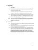
5.7.2 The following table shows the display codes, causes and remedies:
Code
Possible Cause Suggested Remedy
0 Normal Condition No action required
1 Reserved
2 Temperature Sensor off Scale Verify process. Check for open or short
connections.
3 D.O. reading off Scale Verify process. Check for open or short
connections.
4* Memory Loss Call your OMEGA Rep. Or OMEGA
directly
5 Reserved
6 Sensor Fault Check probe membrane for perforation
7 Factory Setting in force, as a Perform procedure according to Section 9.2
result of the ESCAPE procedure
NOTE: Code 4 could be a serious failure so the alarm relay will energize in addition to the red
illumination of the FAIL LED, if DIP switch 5 Bank S1 is OFF.
5.8 Relay A Setpoint
5.8.1 As shipped from the factory, Relay A is configured to control decreasing D.O.
However, you may change the direction of control by changing the position of DIP
switch 4 Bank S1. Please refer to Section 4.8.