MADE IN User’s Guide Shop online at omega.com e-mail: info@omega.com For latest product manuals: omegamanual.
OMEGAnet ® On-Line Service omega.com Internet e-mail info@omega.com Servicing North America: Canada: 976 Bergar Laval (Quebec) H7L 5A1, Canada Tel: (514) 856-6928 FAX: (514) 856-6886 e-mail: info@omega.ca U.S.A.: ISO 9001 Certified One Omega Drive, Box 4047 Stamford, CT 06907-0047 Tel: (203) 359-1660 FAX: (203) 359-7700 e-mail: info@omega.com For immediate technical or application assistance: U.S.A.
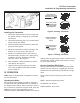
FLR 5000, 6000, 7000, 8000, and 9000 Series Flow Transmitter Installation CAUTION This product should be installed and serviced by technically qualified personnel trained in maintaining industrial class flow instrumentation and processing equipment. I. INTRODUCTION The FLR Flow Transmitter is a state-of-the-art, microprocessor based variable area flow meter.
FLR Flow Transmitter Installation & Programming Instructions II.
FLR Flow Transmitter Installation & Programming Instructions Table 1 - Dimensions A Nominal Port Size 1 B Length in. (mm) C Length in. (mm) D Length in. (mm) E Width in. (mm) F Width in. (mm) G Width in. (mm) H Width in. (mm) I J K Depth Offset Hole Dia. in. (mm) in. (mm) in. (mm) /4 (SAE 6) 6.60 (168) 5.27 (134) 6.41 (163) 6.00 (152) 3.23 (82) 3.00 (76) 4.20 (107) 2.94 (75) 1.51 (38) .31 (8) /2 (SAE 10) 6.60 (168) 5.27 (134) 6.41 (163) 6.00 (152) 3.23 (82) 3.00 (76) 4.
FLR Flow Transmitter Installation & Programming Instructions Installation Recommendations The transmitter is a simple device to install. However, the following measures are recommended for reliable, trouble-free operation: DO - Align pipe accurately. Piping should be accurately aligned and of correct length. The high pressure body of the transmitter can withstand shock and flow/pressure pulsation.
FLR Flow Transmitter Installation & Programming Instructions Schematics The transmitter can be wired in various configurations to allow interface with many different types of data collection and control instrumentation. Schematics 1 & 2 represent typical wiring for a target powered by either AC power or DC supply. Schematics 3 & 4 will be utilized when the flow transmitter is operated with loop-powered process indicators or data loggers that do not have external sensor excitation available. ® Figure 3.
FLR Flow Transmitter Installation & Programming Instructions FLR FLOW INLET PORT Place wrench on transmitter flats on the same side plumbing is being tightened Never place wrench on transmitter flats opposite plumbing being tightened Figure 5. Flow Direction Arrow Installing the Transmitter 1. Disconnect electrical power from the target system before making or changing any transmitter connections. 2. Use 0.05A fast acting fuse if non-current limited power sources are utilized. 3.
FLR Flow Transmitter Installation & Programming Instructions ENTER - The current total can be manually stored in the monitor's flash memory. Press and hold the ENTER key for 2 seconds. The display will respond with a flashing TOTALSVD and then will return to RUN mode. RESET TOTAL - To reset the monitor total display, press the MENU and ENTER keys simultaneously until TOTALRST starts to flash. The TOTALRST will stop flashing and the display will return to RUN mode at the conclusion of the reset procedure.
FLR Flow Transmitter Installation & Programming Instructions Programming Procedures Numeric Value Entry Procedure The FLR Transmitter allows two basic sets of program- Note: If you are already in PROGRAM mode and the desired selection is displayed, proceed to step 3 ming procedures: list item selection and entering below. If you are in PROGRAM mode and the desired numeric values.
FLR Flow Transmitter Installation & Programming Instructions Programming Flow Chart The programming flow chart on pages 10 and 11 will aid understanding of the menu structure of the FLR Flow Transmitter. It will also help with understanding the available configuration selections. Programming Descriptions Display Mode The meter can display RATE (flow rate) or TOTAL (total accumulated flow) or alternate between BOTH rate and total.
FLR Flow Transmitter Installation & Programming Instructions Page 10
FLR Flow Transmitter Installation & Programming Instructions Page 11
FLR Flow Transmitter Installation & Programming Instructions Zero Capture Viscosity The zero position of the meter cone must be set when installing the meter. To capture the zero calibration position, press ENTER at the ZERO CAP prompt. NO will display. Press either arrow key to change to YES, then press ENTER to capture zero. Meter Type Viscosity is used in conjunction with the Meter Size to perform viscosity correction when the Meter type selected is OIL.
FLR Flow Transmitter Installation & Programming Instructions Output Mode The FLR Flow Transmitter offers three analog output modes: • 4–20 mAOutput Signal • 0–5 Volts DC Output Signal • 0–10 Volts DC Output Signal The output mode selected is determined by the type of peripheral device being connected to the FLR Flow Transmitter. The displayed name is OUT MODE and is viewed or changed using the List Item Selection Procedure found on page 8.
FLR Flow Transmitter Installation & Programming Instructions Password WARNING Password protection prevents unauthorized users from changing programming information. Initially the password is set to all zeros. Its displayed name is PASSWORD and is viewed or changed using the Numeric Value Entry Procedure found on page 8. Do not use aromatic hydrocarbons, halogenated hydrocarbons, ketones, or ester based fluids on polycarbonate lens.
FLR Flow Transmitter Installation & Programming Instructions Inspection 1. Frequent inspection should be made. The environment and frequency of use should determine a schedule for maintenance checks. It is recommended that it should be at least once a year. 2. Perform visual, electrical, and mechanical checks on all components on a regular basis. 3.
FLR Flow Transmitter Installation & Programming Instructions Application Information – Pneumatic NOTE: Pressure and temperature readings must be taken at the flow transmitter inlet to ensure accurate correction factors. The pneumatic flow transmitter is calibrated for air in standard cubic feet per minute (scfm) at 1.0 s.g. (70°F @ 100 psi), and liters per second (lps) at 1.0 s.g. (21°C @ 6.9 bar). Figure 10. System Schematic 150 .835 175 .778 30 .962 50 .981 70 1.00 f2= 225 250 .692 .658 150 1.
FLR Flow Transmitter Installation & Programming Instructions Flow vs. Pressure Drop Water Based Fluids PRESSURE DROP, PSI .05-.50 3/4" / 1" 1-10 0.5-5.0 FLOW, GPM 0.1-1.0 0.2-2.0 4-4 3-30 PRESSURE DROP, PSI 1-1/4"/ 1-1/2" 10-150 10-100 10-75 5-50 3-30 0.5 2-20 FLOW, GPM FLOW, GPM PRESSURE DIFFERENTIAL, PSID PRESSURE DROP, PSI .02-.20 1-15 1/2" .10-1.0 PRESSURE DROP, PSI .20-2.
FLR Flow Transmitter Installation & Programming Instructions Water PRESSURE DROP, PSI .05-.50 1-10 0.5-5.0 FLOW, GPM PRESSURE DROP, PSI 0.1-1.0 0.2-2.0 4-40 3-30 2-20 FLOW, GPM 15-150 3" 10-150 10-100 10-75 5-50 3-30 10-100 5-50 FLOW, GPM FLOW, GPM Caustic and Corrosive Liquids 1/4" 1/2" .20-2.0 1/4" PRESSURE DROP, PSI PRESSURE DROP, PSI .10-1.0 1-15 1/2" 1-10 0.5-5.0 0.2-2.0 FLOW, GPM FLOW, GPM 1-1/4"/ 1-1/2" 4-40 3-30 2-20 0.1-2.0 FLOW, GPM Page 18 0.5-5.
FLR Flow Transmitter Installation & Programming Instructions Petroleum Fluids .10-1.0 .02-.20 .05-.50 1-10 0.5-5.0 0.1-1.0 0.2-2.0 3-30 10 2-20 0.2-2.0 0 0 10 20-300 10-200 PRESSURE DROP, PSI 3.0" 10-100 10-75 5-50 3-30 FLOW, GPM 1/2" Reverse Flow 1-10 0.5-5.0 5 FLOW, GPM 10-150 1-1/4"/1-1/2" 5-50 4-40 FLOW, GPM FLOW, GPM PRESSURE DROP, PSI 3/4"/ 1" 1-15 PRESSURE DROP, PSI PRESSURE DROP, PSI PRESSURE DROP, PSI 1/2" .20-2.
FLR Flow Transmitter Installation & Programming Instructions Phosphate Ester .20-2.0 1/4" 1-15 1/2" 6 PRESSURE DROP, PSI PRESSURE DROP, PSI .10-1.0 .02-.20 .05-.5O 4 2 0 0.0 0.5 1-10 0.5-5.0 2 0 FLOW, GPM 5-50 1 2 2.5 4-40 3-30 0.5-5.0 6 2-20 4 1-10 2 0 10-150 1-1/4" / 1-1/2" PRESSURE DROP, PSI PRESSURE DROP, PSI 0 FLOW, GPM 3/4"/ 1" 0.2-2.0 10-100 10-75 5-50 3-30 0 1 2 3 4 5 FLOW, GPM FLOW, GPM 1/2" Reverse Flow 0.2-2.0 0.1-1.
FLR Flow Transmitter Installation & Programming Instructions A.P.I. Oil 1/2" .20-2.0 PRESSURE DROP, PSI PRESSURE DROP, PSI 1/4" .10-1.0 1-15 1-10 0.5-5.0 0.2-2.0 FLOW, GPM FLOW, GPM 3/4"/ 1" 4-40 3-30 1-10 2-20 0.5-5.0 0.2-2.
FLR Flow Transmitter Installation & Programming Instructions Air / Compressed Gases 3-30 15-150 2-20 1-10 0.
FLR Flow Transmitter Installation & Programming Instructions NOTES: Page 23
FLR Flow Transmitter Installation & Programming Instructions NOTES: Page 24
WARRANTY / DISCLAIMER OMEGA ENGINEERING, INC. warrants this unit to be free of defects in materials and workmanship for a period of 13 months from date of purchase. OMEGA’s Warranty adds an additional one (1) month grace period to the normal one (1) year product warranty to cover handling and shipping time. This ensures that OMEGA’s customers receive maximum coverage on each product. If the unit malfunctions, it must be returned to the factory for evaluation.
Where Do I Find Everything I Need for Process Measurement and Control? OMEGA…Of Course! Shop online at omega.