User’s Guide Shop online at omega.com e-mail: info@omega.com For latest product manuals: omegamanual.
OMEGAnet ® Online Service omega.com Internet e-mail info@omega.com Servicing North America: U.S.A.: ISO 9001 Certified Canada: One Omega Drive, P.O. Box 4047 Stamford, CT 06907-0047 TEL: (203) 359-1660 FAX: (203) 359-7700 e-mail: info@omega.com 976 Bergar Laval (Quebec) H7L 5A1, Canada TEL: (514) 856-6928 FAX: (514) 856-6886 e-mail: info@omega.ca For immediate technical or application assistance: U.S.A.
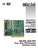
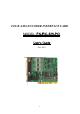
FOUR AXIS ENCODER INTERFACE CARD MODEL Version 2.01, Oct.
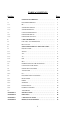
TABLE of CONTENTS Section Page 1 GENERAL DESCRIPTION . . . . . . . . . . . . . . . . . . . . . . . . . . 3 1.1 ENCODER INTERFACE . . . . . . . . . . . . . . . . . . . . . . . . . . . . . 3 1.1.1 IPC . . . . . . . . . . . . . . . . . . . . . . . . . . . . . . . . . . . . . . . . . . . . . . . 3 1.1.2 SOFTWARE OUTPUTS . . . . . . . . . . . . . . . . . . . . . . . . . . . . . . 3 1.1.3 SOFTWARE INPUTS . . . . . . . . . . . . . . . . . . . . . . . . . . . . . . . . 4 1.2 CARD’S HARDWARE I/O .
1. GENERAL DESCRIPTION • The EN-EIC-325-PCI handles four axes of user's encoders. Each user's encoder is directly attached to the Encoder Interface on the card. • The EN-EIC-325-PCI includes eleven logical inputs, and three general outputs. • The EN-EIC-325-PCI is I/O mapped. ENCODER INTERFACE 1.1. Note: Each of the registers IPC, XPC and SPR, mentioned below, represents an unsigned integer 24 bit number ranging from 0 to 16777215.
1.1.3. SOFTWARE INPUTS a. b. Data Request to request an XPC update. For example, upon Data Request on the A axis, the following operation is done: XPC A ⇐ IPC A Notes: 1. Data Request may be applied on a single axis, or (all at once) on: axes pair (A+B or C+D), or all four axes. 2. Besides this software Data Request, there is also a hardware (real-time) Data Request applied on all four axes, as described in section 1.2.1 / ii. Reset to clear the IPC.
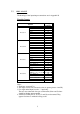
2.2. PIN LAY-OUT The drawings of the input/output connections are in Appendix B.
Logical Inputs D-Type 44 pin No. 16 1 19 34 37 8 26 11 29 44 15 30 Function Input #2 Input #1 Input #3 Input #4 Input #5 Input #11 Input #7 Input #6 Input #8 Input #9 Input #10 GND ENCODERS' EVENT SIGNALS AND GENERAL OUTPUTS Function VExt+ Event Signal General Output VExt– Encoder A Encoder B Encoder C Encoder D Output #1 Output #2 Output #3 D-Type 9 pin No. 1 6 2 7 3 8 4 9 5 Notes: 1. Max. (consumed) current 15 mA + outputs drained current. 2. +/– VExt = 5–24 V.
3. SOFTWARE INTERFACE WITH THE CARD 3.1. INSTALLATION The main files and folders of the software package are as follows: Win95_98 Install.exe WRTdevN.VxD (Ten files: N=0,...,9) ImsEncPci.ocx VB VC WinNT WinRT.sys ImsEic325-PCINT4.reg Win2K EIC325_P.sys ImsEic325-PCIWDM.inf WinXP EIC325_P.sys ImsEic325-PCIWDM.inf OCX for WinNT/2K/XP ImsEncPci.ocx VB VC ReadMe.txt EncPciConst.h EncPciBasicTest DLL for WinNT/2K/XP EIC325PCI.dll EIC325PCI.lib VB VC ReadMe.txt EncPciConst.h EncPciFunctions.
The VB folders The VB folders include an illustration program, which is essential for any user, not only the VB programmer. For any environment you are using – refer to the relevant VB folder. Note: If Visual Basic is NOT installed on your computer, then before running the (VB produced) program EncPciTest.exe (recommended), please verify that: 1. Your WinSysPath folder includes the following two files: * Richtx32.ocx * Riched32.dll 2. The Richtx32.ocx file is registered.
3.1.1. Windows The various Windows folders supply the files required for the driver installation. The Win95/98 driver includes an ActiveX control. The WinNT/2K/XP drivers include two options: an ActiveX control and a DLL. The DLL uses the popular ‘stdcall’ calling convention recognizable by VB, VC, Delphi etc. The ActiveX control and the DLL are implemented by a WinRT-based solution.
WinNT/2K/XP • ActiveX Control Copy the .ocx file from your ‘OCX for WinNT_2K_XP’ folder to your WinSysPath folder and register it by Start, Run, 'regsvr32 WinSysPath\ImsEncPci.ocx'. • DLL Copy the .dll file from your ‘DLL for WinNT_2K_XP’ folder to your WinSysPath folder.
3.1.2. VB Select the ‘VB’ folder that corresponds to your driver installation (section 3.1.1). You'll find here a full illustration in VB 5.0 (named "EncPciTest") that demonstrates how to use the various functions to communicate with the card. There are two versions: one using the ActiveX control, the other using the DLL. The DLL-based version includes an Eic325PciDll.bas file that contains the Declare’s of all the DLL functions.
• • • • The display of the Hardware EventFlags Output reflects what SHOULD be in these outputs analyzing the Software EventFlags Outputs as well as user's operations that may affect the Hardware EventFlags Output, as described in section 3.5.4, functions #22 and #24. Actually, the EncPciTest program simulates card's response and concludes what Hardware EventFlags Output the card should supply. The card reflects in its Hardware General Outputs the status of its software INPUTS.
3.2. INTRODUCTION TO THE FUNCTIONS Each encoders pair is handled by a "chip": Chip #1 includes Encoder Interfaces A and B. Chip #2 includes Encoder Interfaces C and D. The following functions serve the DOS C/C++ programmer as well as the Windows programmer. • The DOS C/C++ programmer should include EncPci.h in his source file, and EncPci.obj in his project. This will make all functions available. • The Windows programmer should use an ActiveX control (Win95/98, WinNT/2K/XP) or a DLL (WinNT/2K/XP).
Supply the Revision ID of current card. Set a LED Get a LED 2 4 (long CardHandle, short LedNumber, short OnOffMode) (long CardHandle, short* RevisionID) 14 Arguments (in C Syntax) (long* CardHandle, short CardIndex) CHIP LEVEL FUNCTIONS 3.4.1. ACTIVE CHIP 3.4. GetLed SetLed GetRevisionID GetCardHandle Name (long CardHandle, short LedNumber, short* OnOffMode) Note: The description of the common arguments is in section 3.
Brief Description Set Active Chip Get Active Chip Test the active chip TestActiveChip GetActiveChip SetActiveChip Name (long CardHandle, short ChipNumber) (long CardHandle, short* ChipNumber) (long CardHandle) 15 Arguments (in C Syntax) Note: The description of the common arguments is in section 3.6 7 6 5 # Tests the active chip. Makes the specified chip active. All the following functions refer to that active chip. Gets the current active chip (Chip1 or Chip2).
Write to chip's outputs. 9 WriteOutputs Name ReadInputs (long CardHandle, short Outputs) 16 Arguments (in C Syntax) (long CardHandle, short* Inputs, short*EncoderEventFlags) Note: The description of the common arguments is in section 3.6 Brief Description Read the inputs of a chip, the EventFlags of its two encoders, and the Voltage Failure. # 8 3.4.2. I/O Full Description Reads 5 or 6 chip's logical inputs, the two flags of its EncoderEvents, and, in case of Chip #1, the Voltage Failure.
Get Encoder Resolution Brief Description Set Encoder Resolution Arguments (in C Syntax) 17 (long CardHandle, short EncoderNumber, short ClocksPerCycle) GetEncoderResolution (long CardHandle, short EncoderNumber, short* ClocksPerCycle) SetEncoderResolution Name Note: The description of the common arguments is in section 3.6 11 10 # ENCODER LEVEL FUNCTIONS 3.5.1. RESOLUTION 3.5. Gets the current selection of the Encoder Resolution (1, 2 or 4 Clocks/Cycle).
Set "reset upon index" Get "reset upon index" 14 15 GetIndexResetsPosition Counter SetIndexResetsPosition Counter GetIndexPulsePolarity SetIndexPulsePolarity Name 18 (long CardHandle, short EncoderNumber, short*EnabledDisabledMode) (long CardHandle, short EncoderNumber, short Polarity) (long CardHandle, short EncoderNumber, short* Polarity) (long CardHandle, short EncoderNumber, short EnabledDisabledMode) Arguments (in C Syntax) Note: The description of the common arguments is in section 3.
Get Set Point 16 17 GetSetPoint SetSetPoint Name 19 (long CardHandle, short EncoderNumber, long* SetPoint) (long CardHandle, short EncoderNumber, long SetPoint) Arguments (in C Syntax) Note: The description of the common arguments is in section 3.6 Brief Description Set Set Point # 3.5.3. SETPOINT Defines the Set Point Register (SPR). Reaching the SPR (i.e., meeting the condition IPC = SPR) may become the trigger of the Event Signal. SetPoint: The desirable SPR.
Get Source of Encoder's EventFlag Set Polarity of Hardware Encoder's EventFlag Get Polarity of Hardware Encoder's EventFlag Brief Description Set Source of Encoder's EventFlag GetEncoderEventFlag Polarity SetEncoderEventFlag Polarity GetEncoderEventFlag Source SetEncoderEventFlag Source Name 20 (long CardHandle, short EncoderNumber, short* Polarity) (long CardHandle, short EncoderNumber, short* EventFlagSource) (long CardHandle, short EncoderNumber, short Polarity).
ClearEncoderEvent Flag 21 (long CardHandle, short EncoderNumber) (long CardHandle, short EncoderNumber, short* OnOffMode) (long CardHandle, short EncoderNumber, short OnOffMode) Note: The description of the common arguments is in section 3.6 24 Get Hold Mode of Hardware Encoder's EventFlag Clear Hardware Encoder's EventFlag 23 GetHoldEncoderEvent Flag Set Hold Mode SetHoldEncoderEvent of Hardware Flag Encoder's EventFlag 22 Clears the hardware Event Signal.
Read Position Counter 27 ReadPositionCounter RequestPositionCounter 22 Arguments (in C Full Description Syntax) (long CardHandle, Clears the Internal Position Counter (IPC) of one or two axes. short EncoderNumber, OutputsMirror: This argument is described within the function short OutputsMirror) WriteOutputs (section 3.4.2, function #9). Note: The eXternal Position Counter (XPC) is NOT affected directly. Run RequestPositionCounter to apply the effect on the XPC, and ReadPositionCounter to read the XPC.
3.6. ARGUMENTS The constants of the arguments are available as follows: * In VB they are included in the example source file. * In VC they are in the EncPciConst.h file in the VC folder; refer to the ReadMe.txt file. * For DOS C/C++, the arguments, along with the headers of the functions, are in the file CPP\EncPci.h. * For other environments, refer to the file More\EncPci.h. It contains the arguments, along with the headers of the functions, coded in C syntax. Transform the code to the proper syntax.
#define TurnOn 1 #define TurnOff 0 // EnabledDisabledMode: #define SetEnabled 1 #define SetDisabled 0 // Polarity: #define ActiveOnHigh 1 #define ActiveOnLow 0 24
APPENDIX A: SPECIFICATION Introduction A half-size PC card. Supports four optical encoders with either Square-wave or Sine output, both linear and rotary types. Directly connected to the encoders and also provides the excitation. Single / Multiple encoder pulses: Interpolation = 1, 2 or 4 (software selectable). Independent operation mode for each axis. General inputs, an index input per each encoder, and an input to request a snapshot of all counters in real-time.
I/O Index input per each axis (indicating Marker/Home/Zero). The user may instruct the card to reset its counter and/or generate an "Event Signal" output upon recognizing the index input. 11 Logical Inputs. The inputs are TTL/CMOS compatible Schmidt trigger single ended. Ten of them are general inputs and one is being used for requesting a real-time counters snapshot of all four channels.
Software Method of communication with PCI bus: I/O ports. Software included: An ActiveX control to communicate with the card in Win95/98/NT/2K/XP. For WinNT/2K/XP thereʼs also a DLL option instead of the ActiveX control. A basic example in Visual C and a detailed example in VB. Example and source code on how to communicate with the board under DOS. General Board dimensions: Half-size PC card. PCI bus for PC. Power (all supplied from the PC bus): +5V: 200 mA max. +12V: 100 mA max. –12V: 50 mA max.
APPENDIX B: DRAWINGS Connector Wiring for the Inputs 28
Connector Wiring for the Outputs 29
APPENDIX C: CARD INSTALLATION ? Install your card only after driver installation (section 3.1.1). Win95/98 1. Shut down your PC (i.e., power off). 2. Insert the new card into a free PCI slot. 3. Turn on your PC. 4. During the Windows 95/98 startup, the following window will appear: Add New Hardware Wizard This wizard searches for new drivers for: PCI Card A device driver is a software program that makes a hardware device work. Click: Next 5.
9. Click: Next 10. Wizard displays: Unsupported Device. Windows has not installed a driver for this device. This is normal either. Click: Finish WinNT 1. Shut down your PC (i.e., power off). 2. Insert the new card into a free PCI slot. 3. Turn on your PC. ? For Win2K/XP instructions please refer to the following pages.
32
33
34
35
36
37
38
APPENDIX D: PRODUCT DEVELOPMENT Main Milestones in Product Development: • • • • Dec. ʼ01: V1.00: Product launching. Apr. ʼ02: V1.02: Support under WinNT/2K/XP (refer to section 3.1.1 & appendix C). May ʼ02: V1.03: In addition to the OCX, a DLL is supplied too (WinNT/2K/XP only). May ʼ03: V2.00: New feature: Option to request a snapshot of the position counters in real-time, using a hardware input (in addition to the veteran software function for this operation).
WARRANTY/DISCLAIMER OMEGA ENGINEERING, INC. warrants this unit to be free of defects in materials and workmanship for a period of 13 months from date of purchase. OMEGA’s WARRANTY adds an additional one (1) month grace period to the normal one (1) year product warranty to cover handling and shipping time. This ensures that OMEGA’s customers receive maximum coverage on each product. If the unit malfunctions, it must be returned to the factory for evaluation.
Where Do I Find Everything I Need for Process Measurement and Control? OMEGA…Of Course! Shop online at omega.