(1*,1((5,1* ,1& IOP-241 24 Channel Digital Input/Output Type II PCMCIA Card Users Manual INTERFACE CARDS FOR PERSONAL COMPUTERS OMEGA ENGINEERING, INC. One Omega Drive P.O. Box 4047 Stamford, CT 06907-4047 Tel: (203) 359-1660 Fax: (203) 359-7700 Toll free: 1-800-826-6342 E-mail: das@omega.com http://www.dasieee.
WARRANTY/DISCLAIMER OMEGA ENGINEERING, INC., warrants this unit to be free of defects in materials and workmanship for a period of 13 months from the date of purchase. OMEGA warranty adds an additional one (1) month grace period to the normal one (1) year product warranty to cover shipping and handling time. This ensures that OMEGA’s customers receive maximum coverage on each product. If the unit should malfunction, it must be returned to the factory for evaluation.
Declaration of Conformity Manufacturer's Name: Omega Engineering, Inc.
OMEGAnet On-line Service: http://www.omega.com Internet e-mail: info@omega.com Servicing North America: USA: ISO 9001 Certified Canada: One Omega Drive, Box 4047 Stamford, CT 06907-0047 Tel: (203) 359-1660 E-mail: info@omega.com 976 Bergar Laval (Quebec) H7L 5A1 Tel: (514) 856-6928 E-mail: info@omega.
United Kingdom: ISO 9002 Certified One Omega Drive, River Bend Technology Drive Northbank, Irlam, Manchester M44 5EX, England Tel: 44 (161) 777-6611 FAX: 44 (161) 777-6622 Toll Free in England: 0800-488-488 E-mail: info@omega.co.uk It is the policy of OMEGA to comply with all worldwide safety and EMC/EMI regulations that apply. OMEGA is constantly pursuing certification of it’s products to the European New Approach Directives. OMEGA will add the CE mark to every appropriate device upon certification.
Table of Contents 1. Introduction ......................................................... 9 1.1 IOP-241 Features . . . . . . . . . . . . . . . . . . . . . . . . . . . . . . . . . . . . . . . . . . . . . . . . . . 9 1.2 System Configuration . . . . . . . . . . . . . . . . . . . . . . . . . . . . . . . . . . . . . . . . . . . . . . 9 2. DOS / Windows 3.x Installation ............................... 2.1 IOP-241 Client Driver for DOS . . . . . . . . . . . . . . . . . . . . . . . . . . . . . . . . . . . .
6. External Connections . . . . . . . . . . . . . . . . . . . . . . . . . . . . . . . . . . . . . . . . . . . . . 32 7. Optional Accessories . . . . . . . . . . . . . . . . . . . . . . . . . . . . . . . . . . . . . . . . . . . . . 33 7.1 CP-1037 Cable Assembly . . . . . . . . . . . . . . . . . . . . . . . . . . . . . . . . . . . . . . . . . 33 7.2 UIO-37 Screw Terminal Block . . . . . . . . . . . . . . . . . . . . . . . . . . . . . . . . . . . . 34 8. Specifications IOP-241 Users Manual . . . . . . .
List of Figures and Tables Figure 1-1. Figure 3-1. Figure 6-1. Figure 7-1. Figure 7-2. Table 1-1. Table 5-1. Table 5-2. Table 5-3. Table 5-4. Table 5-5. Table 5-6. Table 5-7. Table 5-8. IOP-241 System Configuration . . . . . . . . . . . . . . . . . . . . . . . . . . . . . . . . . . . . . . . . . 9 Windows 95/98 Resource Settings . . . . . . . . . . . . . . . . . . . . . . . . . . . . . . . . . . . . . 21 IOP-241 33-Pin Connector . . . . . . . . . . . . . . . . . . . . . . . . . . . . . . . . . . . . . . .
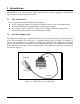
1. Introduction The IOP-241 is a 24 channel digital input/output card for systems equipped with PCMCIA Type II and/or Type III expansion sockets. 1.1 IOP-241 Features 1.2 PC Card Standard Specification 2.
2. DOS / Windows 3.x Installation Two configuration software programs are provided with the IOP-241: a Client Driver and a card Enabler. Both of these programs are executed from DOS (before entering Windows) and allow operation of the IOP-241 in both the DOS and Windows 3.x environments. For optimal operation, the Client Driver is the preferred method of installation and configuration. The table below highlights the differences between these programs.
2.1.1 Client Driver Installation The following procedure is used to install the IOP-241 Client Driver: 1. Copy the file IOP241CL.SYS from the customer software CD-ROM directory PCMCIA\DOS\CLIENTS onto the root directory of the system hard drive. 2. Using an ASCII text editor, open the system CONFIG.SYS file located in the root directory of the boot drive. 3. Locate the line(s) in the CONFIG.SYS file where the Card and Socket Services software is installed. 4.
2.1.2 Command Line Options The Client Driver accepts up to eight command line arguments from the user to determine the configuration of the IOP-241. If any arguments are provided, the Client Driver will attempt to configure the IOP-241 with the options specified in the order they are entered on the command line. Each argument must be enclosed in parenthesis and must be separated from other arguments by a space on the command line.
2.1.2.4 Example 4 DEVICE = C:\IOP241CL.SYS (i11,b300) A single command line argument is provided. Because the parameter order is not significant, the Client Driver will attempt to configure an IOP-241 inserted into any socket with a base address of 300H and IRQ 11. If address 300H or IRQ 11 are unavailable, the IOP-241 will not be configured. 2.1.2.5 Example 5 DEVICE = C:\IOP241CL.SYS (b300,i5) (i10) ( ) Three command line arguments are provided.
2.1.3 Common Problems 2.1.3.1 Generic Client Drivers Many Card and Socket Services packages include a generic client driver (or SuperClient) which configures standard I/O devices. If one of these generic client drivers is installed, it may configure the IOP-241 causing the client driver to fail installation. In these cases, the user should do one of the following: 1. Modify the operation of the generic client driver to disable the configuration of modem/serial port cards.
2.2 IOP-241 Enabler for DOS For systems that are not operating PCMCIA Card and Socket Services software, the IOP-241 DOS Enabler may be used to enable and configure the card. This Enabler, IOP241EN.EXE, will operate on any DOS system using an Intel 82365SL or PCIC compatible PCMCIA host adapter including the Cirrus Logic CL-PD6710/6720, the VLSI VL82C146 and the Vadem VG-365. IMPORTANT: In order to use the IOP-241 Enabler for DOS, the system MUST NOT be configured with Card and Socket Services software.
2.2.1 Enabler Installation The following procedure is used to install the IOP-241 Enabler: 1. Copy the file IOP241EN.EXE from the customer software CD-ROM (directory=PCMCIA\DOS\ENABLERS) onto the root directory of the system hard drive. 2. Using an ASCII text editor, open the system's CONFIG.SYS file located in the root directory of the boot drive. 3. Locate the line(s) in the CONFIG.SYS file where the Card and Socket Services software is installed. 4.
2.2.2 Command Line Options To configure an IOP-241, the Enabler requires one command line argument from the user to determine the configuration of the card. This argument must be enclosed in parenthesis and within the argument, any or all of the following parameters may be specified using a comma (no spaces) to separate each parameter: s socket Specifies which PCMCIA socket the IOP-241 must be inserted into for this configuration argument to be used. “Socket” must be in the range of 0 - 15.
2.2.2.3 Example 3 DEVICE = C:\IOP241EN.EXE (i10,b340,s1) The Enabler will configure the IOP-241 in socket 1 with a base address of 340H and IRQ 10 using a configuration memory window at segment D000. Note that the parameter order is not significant. 2.2.2.4 Example 4 DEVICE = C:\IOP241EN.EXE (s0,b300,i3,wd8) The Enabler will configure the IOP-241 in socket 0 with a base address of 300H and IRQ 3 using a configuration memory window at segment D800. 2.2.2.5 Example 5 DEVICE = C:\IOP241EN.
2.2.3.3 Card and Socket Services Software In order to use the IOP-241 Enabler for DOS, the system MUST NOT be configured with Card and Socket Services software. If Card and Socket Services software is installed, the IOP-241 Enabler may interfere with its operation and with the device(s) it controls. For systems configured with Card and Socket Services, the IOP-241 Client Driver is the recommended method of configuration. 2.3 After Completing Configuration The IOP-241 is now configured and ready for use.
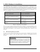
3. Windows 95/98® Installation To allow easy configuration of the IOP-241, a Windows 95/98 "INF" configuration file has been written for the hardware, (DAQPCARD.INF). 3.1 Installing the IOP-241 Under Windows 95/98 1. Insert the IOP-241 into any available PC Card socket. 2. The first time a new PC Card type is installed the New Hardware Found window opens. After this first installation Windows 95/98 will automatically detect and configure the card.
3. Open the Properties dialog box for the IOP-241, then click the Resources tab to view the Input/Output Range and Interrupt Request resource allocations, (see Figure 3-1). 4. To access the IOP-241, use these system resources allocated by Windows 95/98 or see Changing Resource Settings with Device Manager. 3.3 Changing Resource Settings with Device Manager 1. Start the Windows 95/98 Device Manager. 2. Double click on the hardware class Data_Acquisition to list hardware devices in the class.
5. To modify either of the resource settings click the resource name and click the Change Setting button. 6. An Edit Resource window will open. Inside the Edit Resource window click on the up/down arrows to the right of the resource value. This scrolls you through all of the allowable resources for your hardware. Pay attention to the Conflict Information at the bottom of the window. Do not select a resource that causes a conflict with any other installed hardware. 7.
4. Theory of Operation 4.1 I/O Port Description The 24 digital I/O channels provided by the IOP-241 are grouped into three different ports with each port containing eight digital I/O channels. These three ports are controlled via the Data Port A Control Register, Data Port B Control Register and Data Port C Control Register. In all three registers, each bit corresponds to one data line. The Data Port A Control Register is used to access data lines DATA7 - DATA0.
4.2 Port C Interrupt Description The eight Port C I/O channels (DATA23 - DATA16) may also be configured as interrupt sources. If any of these eight I/O channels are used to generate an interrupt, the I/O channel must be configured for input by latching the appropriate bit in the Data Port C Control Register to '1'. The interrupt must also be enabled by setting the appropriate bit in the Port C Interrupt Enable Register.
5. Register Descriptions The program registers of the IOP-241 occupy eight adjacent bytes of I/O address space. These registers must be programmed to control the operation of the IOP-241.
5.2 Data Port B Control Register (Base + 1) The Data Port B Control Register contains the control bits for I/O channels DATA8 - DATA15. Each I/O channel may be individually programmed for input by writing a '1' to the appropriate bit of this register.
5.4 Port C Interrupt Enable Register (Base + 5) INT7 - INT0 may be enabled by writing the appropriate bits in the Port C Interrupt Enable Register. The corresponding I/O channel must be configured as an input channel via the Data Port C Control Register if an interrupt is to be generated. If an I/O channel is configured as an interrupt source (INT7 - INT0), the I/O channel continues to be a standard data input channel (DATA23 - DATA16) and may be read just as any other input signal is read.
5.5 Interrupt Mode Control Register (Base + 6) The mode of both the external interrupt and the Port C interrupts may be controlled with the Interrupt Mode Control Register. The upper nibble (4 bits) and lower nibble (4 bits) of the Port C interrupts may be configured separately. The external interrupt may also be enabled by writing this register.
5.7 Interrupt Acknowledge Register (Write Only) (Base + 7) Writing a '1' to any bit in the Interrupt Acknowledge Register will acknowledge the interrupt generating condition which was represented in the corresponding bit of the Interrupt Status Register. If a '1' is written to a bit in the Interrupt Acknowledge Register and the corresponding interrupt generating condition is not present, then the appropriate bit in the Interrupt Status Register will be reset (set to '0').
(2) External Interrupt Source (a) The following must be programmed: (i) (ii) (b) Interrupt generated if ExtIntStat of Interrupt Mode Control Register is '1'. (c) '1' in ExtIntStatus is reset to '0' if the following two requirements are satisfied: (i) (ii) 5.9 Interrupt source enabled via Interrupt Mode Control Register. Mode selected via Interrupt Mode Control Register. Interrupt acknowledged by writing ExtIntAck with '1'. Condition which caused interrupt is no longer present.
5.10 Programming Example The following C program segment demonstrates how to program an IOP-241 located at I/O base address 300h. Port A will be programmed as output, and 55h will be latched at Port A. Port B will be configured with it's upper 3 bits as output and it's lower five bits as input. The upper three bits will be latched with 010b. Port C will be configured as input. Interrupts will be enabled as explained in the program comments.
6. External Connections The IOP-241 is fitted with a 33-pin 0.8mm shielded connector with the pins assigned as shown in Figure 6-1 below. 1 5 10 25 30 33 QUATECH INC. 20 IOP-241 15 GND DATA0 DATA1 DATA2 DATA3 DATA4 DATA5 DATA6 DATA7 GND DATA8 DATA9 DATA10 DATA11 DATA12 DATA13 DATA14 DATA15 GND DATA16/INT0 DATA17/INT1 DATA18/INT2 DATA19/INT3 DATA20/INT4 DATA21/INT5 DATA22/INT6 DATA23/INT7 GND EXT_IRQ GND GND GND GND Figure 6-1.
7. Optional Accessories 7.1 CP-1037 Cable Assembly An optional cable assembly, Omega product number CP-1037, is available to convert the IOP-241's 33-pin 0.8mm I/O connector to a standard D-37 male connector. The first 31 connections on the IOP-241 map directly to the first 31 pins of the D37 connector. Note that two of the IOP-241 ground connections (pins 32 and 33) are not available when using the CP-1037. Figure 7-1 illustrates the D37 connector pin assignments.
7.2 UIO-37 Screw Terminal Block The UIO-37 Screw Terminal Block shown in Figure 7-2 connects directly to the optional CP-1037 cable assembly to provide users with a screw terminal interface. The D37 connector of the CP-1037 connects directly to the 37 screw terminal blocks of the UIO-37. Each screw terminal is numbered for easy reference.
8. Specifications Bus Interface Physical Dimensions PCMCIA PC Card Standard 2.1 compliant Type II PCMCIA card (5mm) Power Requirements +5 volts 7.33 mA Typical (all outputs 'off') 12.38 mA Maximum (all outputs 'off') 36.38 mA Maximum (all outputs 'on') Digital Input/Output TTL Compatible Current Source/Sink (at 25° C) Sink 6mA(min) at 0.33V Sink 20mA(max) at 1.0V Source 1.
IOP-241 Users Manual Version 2.30 January 25, 1999 Part No.