User’s Guide Shop online at www.omega.com e-mail: info@omega.
OMEGAnet ® Online Service www.omega.com Internet e-mail info@omega.com Servicing North America: USA: ISO 9001 Certified Canada: One Omega Drive, Box 4047 Stamford CT 06907-0047 Tel: (203) 359-1660 e-mail: info@omega.com 976 Bergar Laval (Quebec) H7L 5A1, Canada Tel: (514) 856-6928 e-mail: info@omega.
LV860 LEVEL SENSOR Please follow these installation, connection and adjustment instructions carefully. Failure to comply with these instructions or misuse of this equipment will void your warranty coverage.
LV860 LEVEL SENSOR NOTES: ii
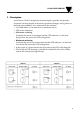
LV860 LEVEL SENSOR 1 - Description Level Sensor LV860 is designed to monitor liquids, granules and powder. It operates on the principle of electrical capacitance changes arising when an electrode surrounded by air is immersed in the medium. • Available either as a maximum or a minimum sensor. • LED status indication • Minimum switching Normally the sensor is immersed and the LED indicates. As the level drops below the sensor the LED extinguishes.
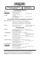
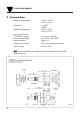
LV860 LEVEL SENSOR 2 - Technical Data Medium temperature Short-time Ambient temperature Pressure resistance: PTFE Teflon® fitting Polyamide 12 fitting Response delay Degree of protection Input voltage -20°C to +130°C -4°F to +266°F to +150°C +302°F -20°C to +85°C -4°F to +185°F max. 2 bar (29.4 PSI) max. 25 bar (367.5 PSI) approx.
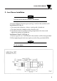
LV860 LEVEL SENSOR 3 - Level Sensor Installation NOTE The Level Sensor may be installed in any attitude. 1. Ensure sufficient clearance space (see fig. 1 and 2) in the container wall. Installation STD (fig. 1): • The screw joint comprises a sleeve, a spring and a slotted nut. • The sleeve must be welded into the container wall. 2. Place the level sensor (without sealing compound) in the sleeve and tighten the spring and slotted nut. Installation G1A or 1" NPT (fig.
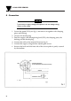
LV860 LEVEL SENSOR 4 - Connection CAUTION Check that the supply voltage corresponds with the voltage rating shown on the system. 1. Loosen the gland (PG9) (see fig. 1) and remove it together with clamping piece and bushing. 2. Unscrew the female plug. 3. Feed the supply cable through the gland (PG9), the clamping piece, the bushing and the female plug. 4. Connect the cable to the terminal block (see fig. 3). 5. Connect the supply voltage before adjusting the sensor. 6.
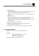
LV860 LEVEL SENSOR 7. Minimum sensor • Turn the potentiometer screw clockwise until the LED extinguishes. Then slowly turn counterclockwise (+) until the LED indicates. Adjust the screw a further full turn clockwise (-) to compensate for any tolerance. 8. Maximum sensor • Turn the potentiometer screw clockwise until the LED indicates. Then slowly turn counterclockwise (+) until the LED extinguishes. Adjust the screw a further full turn counterclockwise (+) to compensate for any tolerance. 9.
LV860 LEVEL SENSOR NOTES: 6
WARRANTY/DISCLAIMER OMEGA ENGINEERING, INC. warrants this unit to be free of defects in materials and workmanship for a period of 13 months from date of purchase. OMEGA’s Warranty adds an additional one (1) month grace period to the normal one (1) year product warranty to cover handling and shipping time. This ensures that OMEGA’s customers receive maximum coverage on each product. If the unit malfunctions, it must be returned to the factory for evaluation.
Where Do I Find Everything I Need for Process Measurement and Control? OMEGA…Of Course! Shop online at www.omega.