LVU40 and LVRD500 Series Ultrasonic Level Sensor and Radar Level Sensor INSTRUCTION SHEET M4214/0605 Shop online at: omega.com e-mail: info@omega.com For latest product manuals: omegamanual.
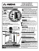
Instruction Manual For LVU and LVRD Series Ultrasonic and Radar Sensors Inter-Connection Diagram Top View of Sensor (Access Cover Removed) +8 12– 30 VDC -- 7 6 DC Power Input Note - TB #7 is Connected to TB #4 Control Panel Fastening Screw FCC INFORMATION TO RADAR USERS NOTE: This equipment has been tested and found to comply with the limits for a Class A digital device, pursuant to Part 15 of the FCC Rules.
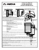
Instruction Manual For LVU and LVRD Series Ultrasonic and Radar Sensors Fig. # 2 RS485 Connection -- 4 Shield 3 A/TX 2 Red 1 2 3 4 5 6 7 8 9 DB9 WHT. or BLK. L1 8 L2 / N 7 Sensor Terminal L1 8 L2/N 7 GND. 6 + 5 SHIELD Sensor Terminal Fig. # 1 RS232 Connection 6 7 8 9 GND. 6 + 5 -- 4 Shield 3 A/TX 2 Connect to Serial Port of PC ,use Extension Cable length as required ,Refer to Fig.# 1 or # 2 For Wiring 1 2 3 4 5 To Power Source FUSE Red DB9 WHT. or BLK.
Servicing Europe: OMEGAnet ® Online Service omega.com Internet e-mail info@omega.com Servicing North America: U.S.A.: ISO 9001 Certified Canada: One Omega Drive, Box 4047 Stamford, CT 06907-0047 Tel: (203) 359-1660 e-mail: info@omega.com FAX: (203) 359-7700 976 Bergar Laval (Quebec) H7L 5A1, Canada Tel: (514) 856-6928 FAX: (514) 856-6886 e-mail: info@omega.