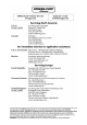
Contents 1. Hardware Checklist............................................................................3 2. General Information...........................................................................4 3. Communicating with your Logger ...................................................5 4. Quick Start Example..........................................................................8 5. Download Process Explained.........................................................12 6. Menu and Navigation........
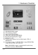
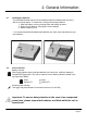
1. Hardware Checklist B A D C E H F G A) B) C) D) E) F) G) OM-SQ2020/2040 Logger CD containing software User’s Guide (this booklet) USB Cable (OM-SQ-USB-CABLE) Mounting bracket/stand for logger Batteries, 6 x AA Current shunt resistors for 4 to 20mA inputs, 10R x 4 (OM-SQ-CS) H) Connectors: 6 way x 4 (OM-SQ-TB6), 4 way (OM-SQ-TB4), 3 way (OM-SQ-TB3), with cable ties Note: OM-SQ2040 Logger is supplied with 4 extra 6 way connectors as above (OM-SQ-TB6). Version 1.
2. General Information 2.1 Installing the batteries The OM-SQ2020/2040 uses six AA size alkaline batteries located under the removable cover shown below. To insert new or change the existing batteries: 1. Open the battery cover by pushing down and sliding as shown. 2. Insert six AA* batteries, ensuring the correct polarity. 3. Refit the battery cover * It is recommended that all replacement batteries are of the same manufacturer, type and condition. 2.
3. Communicating with your Logger 3.1 Installing the Software For detailed installation instructions please see the supplied ‘Software Installation Guide’ supplement. For quick installation please see the steps below; 1. 2. 3. 4.
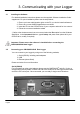
USB Connect one end of the supplied USB lead to the USB port on the logger and the other end to a USB port on the PC. On detection of the logger the PC will launch the driver installation wizard. Win 2000/XP - During the installation the USB drivers were pre-installed so the wizard will automatically locate the driver. On the ‘Found New Hardware Wizard’ select ‘No, not this time’ and for all the other screens select ‘Next’ to complete the installation. 28923 Version 1.
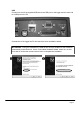
Win 98SE - Select Search for the best driver for your device (Recommended), Click Next and follow the instructions illustrated below. Select Continue Anyway on the Hardware Installation warning which refers to Windows Logo testing. Once the driver installation has completed you are ready to communicate to your logger. If you experience any problems refer to Troubleshooting->20XX USB Drivers in OMEGALOG® help.
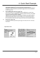
4. Quick Start Example After installing OMEGALOG® an example setfile will be installed within the OMEGALOG® installation directory. The example file will log the internal temperature of the logger. In order to familiarise yourself with the logger the novice user may find this example Setup useful. 4.1 Startup OMEGALOG® and Select Logger Type Click on the shortcut icon on your desktop to launch OMEGALOG® or select it from your start menu.
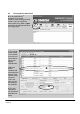
4.3 Running Quick Start Demo In the OMEGALOG® Assistant click ‘Logger Setup’ to enter the Logger Setup screen. From here open the demo setfile using File -> Open and select the appropriate file for your logger type. The Logger Setup screen is now visible, from here you will be able to set up your logging requirements. Within the Actual Channels tab scroll down the Sensor Type column to Ref. Junction 1. This is the input you will be reading in this example.
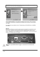
Click to send setup to logger and start logging. Let the unit log for a few minutes. Click for OMEGALOG® Assistant. Click if you wish to meter the input in Real Time. Click on Logger Control icon to pause or stop the logging process. In the Logger Control window you can view relevant information on the state of the logger. To stop logging click on the stop button. To Download the logger click on the ‘Download Data’ icon from the OMEGALOG® Assistant. 28923 Version 1.
In this screen you can now download the Data File and invoke the Export Wizard or download the Data File via Analysis* (See page 10 for further information). The data File is given a unique name (e.g. 28162735.D20). An explanation of the file name is shown on the right; this shows the date and start time In this example you will download and view the Data in the Analysis* window. Start by selecting the Data File and Graph Data action, then click Download Selected File(s).
5. Download Process Explained Logger Data Files (.d20) (.d20) Data File in external MMC/SD card Microsoft Excel Analysis (.xls) Analysis File (Plus Only) Reader Export ® OMEGALOG (.csv) Comma Separated Values The Diagram above shows the download process. Data in the logger is written to the internal memory and may be downloaded by OMEGALOG®. Before the data can be viewed it must be converted by OMEGALOG® for Analysis or exported to .csv or .xls format depending on the PC software being used.
6. Menu and Navigation 6.1 Control Panel The illustration below shows the navigation controls in more detail. LEFT NAVIGATION RIGHT NAVIGATION ENTER/CONFIRM & POWER ON ESCAPE/BACK (reverts to previous Menu) To use the OM-SQ2020/2040 control panel press , the opening display will be shown (see right). The display timeout is preset to 10 seconds, however this can be changed by selecting the Configuration tab within the Logger Setup window of OMEGALOG®. Version 1.
6.2 28923 Control panel menu Detailed below is a basic explanation of the top menu structure. For more information on the whole menu structure please refer to the Help->Help Content->Loggers within OMEGALOG®. 6.3.1 Log Control In this menu you can Arm (activate) or Disarm (deactivate) the logger. 6.3.2 Meter Here you can view each channel in Real Time (at 1-2Hz). Use the enter key to auto scroll through the channels. 6.3.
7. Connections Analog Inputs Rear view of ANALOG connectors Rear view of ANALOG connectors NOTE: Blocks G to K as shown above are only available on OM-SQ2040 loggers. As the wiring configuration is dependant upon the sensor type used, it is displayed in OMEGALOG ® during the setup. Follow the wiring diagram to attach the required sensor. If you would like to print the diagrams in more detail or view at a later stage select ‘File > Print from Logger Setup’.
High Voltage Input Sensor Power Wiring Block E Unregulated Logger Supply Output Block F Negative Regulated 5V Output V1(+ve) V2(-ve) V1(-ve) V2(+ve) I/O Socket Wiring ALARM O/P EVENT/STATE I/P 1-8 PIN 1 -ve SLOW PULSE I/P 1-2 FAST PULSE I/P 1-2 +ve Auxiliary Output Max.
8. Accessories OMEGA Engineering supplies a wide range of accessories to compliment the range of OM-SQ2020\2040 data loggers. These include GSM Modem and Ethernet converters and wireless adapter as shown below, all of which allow you to contact any OM-SQ2010 data logger remotely or where no land line exists. All are very easy to install and connect directly to the logger via RS232. If you need any further details or wish to make a purchase please contact OMEGA Engineering.
Part No: Software packages for set-up, transfer and data analysis: OMEGALOG® Plus Provides full data analysis, on-line graphing, meter to Excel and export to Excel OMEGALOG® Plus Multi-User License Unlimited use of OMEGALOG® within a single organization.
9. Specifications ANALOG INPUTS Basic accuracy (5-45°C): ..............................................± (0.05% readings + 0.025% range) Common mode rejection: ...........................................................................................100dB Input impedance: ...................................................................................................> 1MOHM Linearity: ..................................................................................................................0.
POWER CONSUMPTION @ 9V Sleep mode: ..............................................................................................................<600µA Logging: ..............................................................................................................40 - 120mA DIMENSIONS AND WEIGHT 2020 Logger Dimensions: ...................................................................................W235 x D175 x H55 mm Weight: ........................................................................
Personal Notes: Version 1.