
Computer Hardware User Manual
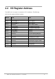
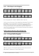

The PC I/O port mapping is given below.
ADDRESS DEVICE ADDRESS DEVICE
000-1FF PC reserved 320-32F XT Hard Disk
200-20F Game/control 378-37F Parallel Printer
210-21F XT Expansion Unit 380-38F SDLC
238-23F Bus Mouse/Alt. Bus Mouse 3A0-3AF SDLC
278-27F Parallel Printer 3B0-3BF MDA/Parallel Printer
2B0-2DF EGA 3C0-3CF EGA
2E0-2E7 AT GPIB 3D0-3DF CGA
2E8-2EF Serial Port 3E8-3EF Serial Port
2F8-2FF Serial Port 3F0-3F7 Floppy Disk
300-31F Prototype Card 3F8-3FF Serial Port
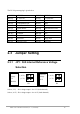
2.3 Jumper Setting
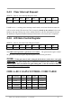
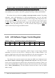
2.3.1 JP1 : D/A Internal Reference Voltage
Selection
JP1
(-5 V)
(
-10 V
)
Reference
Voltage
-5 V
(Default)
(
-10 V
)
(-5 V)
JP1
Reference
Voltage
-10 V
Select (-5 V) : D/A voltage output = 0 to 5 V (both channels)
Select (-10 V) : D/A voltage output = 0 to 10 V (both channels)
OME-A-8111 Hardware Manual (ver.1.1, Jul/2003) 10