
Computer Hardware User Manual
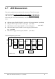

2.7.1 A/D conversion flow
Then the user must decide which A/D conversion mode will be used. The software driver
supports three different modes. The user can control the A/D conversion by polling mode
very easily (sec. 2.4.9). It is recommended to use the software driver if using interrupt or
DMA mode.
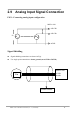
The analog input signals come from CN1.
The multiplexer can accept 8 single-ended lines into the gain control module. The gain
control module also needs settling time if the gain control code changed. Because the
software doesn’t monitor the settling time, the user should reserve enough settling time
if switching from one channel to the next (sec. 2.4.6).
The output of the gain control module feeds into the A/D converter. The A/D converter
needs a trigger signal to start an A/D conversion cycle. The OME-A-8111 supports
software trigger or pacer trigger mode.
2.7.2 A/D Conversion Trigger Modes
OME-A-8111 supports two trigger modes.
1 : Software Trigger :
Writes any value to the A/D software trigger control register, BASE+A, will initiate an
A/D conversion cycle. This mode is very simple but very difficult to control the
sampling rate.
2 : Pacer Trigger Mode :
The block diagram of the pacer timer is shown in section 2.6. The pacer timer can give
very precise sampling rates.
OME-A-8111 Hardware Manual (ver.1.1, Jul/2003) 22