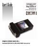
User’s Guide Shop online at www.omega.com e-mail: info@omega.
OMEGAnet ® Online Service www.omega.com Internet e-mail info@omega.com Servicing North America: USA: ISO 9001 Certified Canada: One Omega Drive, P.O. Box 4047 Stamford CT 06907-0047 TEL: (203) 359-1660 e-mail: info@omega.com 976 Bergar Laval (Quebec) H7L 5A1, Canada TEL: (514) 856-6928 e-mail: info@omega.
Contents INTRODUCTION.......................................................................................................... 1 OVERVIEW ...................................................................................................................1 W HAT ’S INCLUDED....................................................................................................1 FACTORY DEFAULT SETTINGS................................................................................1 CARD SETUP ....................
APPENDIX F - SILK-SCREEN .................................................................................18 APPENDIX G - COMPLIANCE NOTICES.............................................................19 FEDERAL COMMUNICATIONS COMMISSION STATEMENT ...............................19 EMC DIRECTIVE STATEMENT ..............................................................................19 Figures Figure 1- Dip switch SW1, RS-422 ....................................................................
Introduction Introduction Overview The OMG-CONV-485-ISO is a single channel RS-232 to RS-422/485 asynchronous converter. It provides one field selectable RS-422/485 serial port supporting asynchronous data rates up to 115.2K bps. The OMG-CONV-485ISO is self-powered allowing it to correctly drive multi-drop RS-485 networks. Configure the port as RS-422 for long distance device connections up to 4000ft. where noise immunity and high data integrity are essential.
Card Setup Card Setup RS-485 Enable Modes RS-485 is ideal for multi-drop or network environments. RS-485 requires a tri-state driver that will allow the electrical presence of the driver to be removed from the line. The driver is in a tri-state or high impedance condition when this occurs. Only one driver may be active at a time and the other driver(s) must be tri-stated. The output modem control signal Request To Send (RTS) is typically used to control the state of the driver.
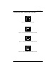
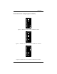
Card Setup Communication Mode Examples (Dip switch SW1) OFF ON 1 2 Figure 1- Dip switch SW1, RS-422 OFF ON 1 2 Figure 2 – Dip switch SW1, RS-485 ‘Auto’ Enable OFF ON 1 2 Figure 3 – Dip switch SW1, RS-485 ‘RTS’ Enable OFF ON 1 2 Figure 4 – Dip switch SW1, RS-485 ‘Data’ Enable OMG-CONV-485-ISO Page 3
Card Setup Line Termination and Receiver Echo Off/On Typically, each end of the RS-485 bus must have a line-terminating resistor (RS-422 terminates at the receive end only). A 120-ohm resistor is across each RS-422/485 input in addition to a 1K-ohm pull-up/pull-down combination that biases the receiver inputs. Dip switch SW2 allows customization of this interface to specific requirements. Each dip switch position corresponds to a specific portion of the interface.
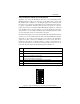
Card Setup Electrical Interface Examples (Dip switch SW2) OFF ON 1 2 3 4 5 6 Figure 6 – RS-422 with Termination and Receiver Echo OFF ON 1 2 3 4 5 6 Figure 7 – RS-485 2-wire with Termination and Receiver No Echo OFF ON 1 2 3 4 5 6 Figure 8 – RS-485 2-wire no Termination and Receiver No Echo OMG-CONV-485-ISO Page 5
Installation Operating System Installation (For Windows Users) RS-422/RS-485 Four Wire Master/RS-485 Two Wire Auto Mode Installation If your application is 4-wire Full Duplex RS-422 or 4-Wire RS-485 Master, where control of the transmitter is not required, or 2-wire RS-485 and you intend to use the Auto Mode to control the transmitter, simply connect the OMG-CONV-485ISO to an existing RS-232 COM: port. This will utilize the Operating System Serial Driver to control the COM: port.
Installation RS-485 Two-Wire and RS-485 Four-Wire Slave Installation If your application is 2-wire Half-Duplex RS-485 or 4-Wire Full-Duplex RS-485 Slave that requires control of the transmitter, the OMG-CONV-485-ISO provides 3 methods of control. The first method is ‘Auto Enable’ which uses an onboard microcontroller to sense the baud rate and control the transmitter enable. This mode assumes a minimum baud rate of 1200bps and a word length of 10 bits.
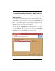
Installation Once the software installation is complete, the port must be configured for ‘RTS Enable’. This is accomplished by using the Device Manager in Windows 9X, ME, and Windows 2000. The port that the OMG-CONV-485-ISO is attached must be selected under Ports (COM & LPT). Access the ‘RTS Enable’ checkbox via the ‘Advanced’ dialog. In Windows NT, the ‘Advanced Ports’ applet should be used for configuration.
Installation System Installation The OMG-CONV-485-ISO can be connected to any existing RS-232 port. A cable such as the CA-177 can be used to attach the OMG-CONV-485-ISO DB-25F to the PC’s DB-9M connector. 1. 2. 3. 4. 5. 6. Locate an existing RS-232 COM: port and connect the OMG-CONV-485-ISO. With the OMG-CONV-485-ISO case open, configure dip switches SW1 and SW2 for your application. Connect the wiring to your external device via the provided 6-position screw terminal.
Technical Description Technical Description The OMG-CONV-485-ISO converts an existing RS-232 serial port into a field selectable RS-422/485 port for industrial automation and control applications. Connector Pin Assignments RS-232 Signals (DB-25 Female) Signal GND RD CTS DSR DCD RI TD RTS DTR Name Ground Receive Data Clear To Send Data Set Ready Data Carrier.
Specifications Specifications Environmental Specifications Specification Temperature Range Humidity Range Operating 0º to 50º C (32º to 122º F) 10 to 90% R.H. Non-Condensing Storage -20º to 70º C (-4º to 158º F) 10 to 90% R.H. Non-Condensing Manufacturing • All Printed Circuit boards are built to U. L. 94V0 rating and are 100% electrically tested. These printed circuit boards are solder mask over bare copper or solder mask over tin nickel. Mean Time Between Failures (MTBF) Greater than 150,000 hours.
Appendix A - Troubleshooting Appendix A - Troubleshooting Serial Utility test software is supplied with the adapter and will be used in the troubleshooting procedures. By using this software and following these simple steps, most common problems can be eliminated without the need to call Technical Support. 1. The OMG-CONV-485-ISO is a level converter and therefore requires no system resources such as I/O ports or IRQ’s. The I/O resources of the host RS-232 COM: port will be used to access the port. 2.
Appendix B - How To Get Assistance Appendix B - How To Get Assistance Please refer to Appendix A - Troubleshooting prior to calling Technical Support. 1. Read this manual thoroughly before attempting to install the adapter in your system. 2. When calling for technical assistance, please have your user manual and current adapter settings. If possible, please have the adapter installed in a computer ready to run diagnostics. 3. Omega Engineering maintains a Home page on the Internet.
Appendix C – Electrical Interface Appendix C - Electrical Interface RS-232 Quite possibly the most widely used communication standard is RS-232. This implementation has been defined and revised several times and is often referred to as RS-232 or EIA/TIA-232. The IBM PC computer defined the RS-232 port on a 9 pin D sub connector and subsequently the EIA/TIA approved this implementation as the EIA/TIA-574 standard.
Appendix C – Electrical Interface RS-485 RS-485 is backwardly compatible with RS-422; however, it is optimized for partyline or multi-drop applications. The output of the RS-422/485 driver is capable of being Active (enabled) or Tri-State (disabled). This capability allows multiple ports to be connected in a multi-drop bus and selectively polled. RS-485 allows cable lengths up to 4000 feet and data rates up to 10 Megabits per second. The signal levels for RS-485 are the same as those defined by RS-422.
Appendix D – Ground Loop Phenomenon Appendix D - Ground Loop Phenomenon What is Ground Loop? Ground loop Phenomenon occurs when two (or more) pieces of equipment are connected together with a common ground and a different ground potential exists at each location. This current can cause the connected equipment to experience noise that in turn causes data transmission errors. In the extreme this ground current can cause equipment malfunction or even destruction.
Appendix E - Asynchronous Communications Appendix E - Asynchronous Communications Serial data communications implies that individual bits of a character are transmitted consecutively to a receiver that assembles the bits back into a character. Data rate, error checking, handshaking, and character framing (start/stop bits) are pre-defined and must correspond at both the transmitting and receiving ends.
Appendix F - Silk-Screen Appendix F - Silk-Screen 2.688 in 2.
Appendix G - Compliance Notices Appendix G - Compliance Notices Federal Communications Commission Statement FCC - This equipment has been tested and found to comply with the limits for Class A digital device, pursuant to Part 15 of the FCC Rules. These limits are designed to provide reasonable protection against harmful interference when the equipment is operated in a commercial environment.
WARRANTY/DISCLAIMER OMEGA ENGINEERING, INC. warrants this unit to be free of defects in materials and workmanship for a period of 13 months from date of purchase. OMEGA’s WARRANTY adds an additional one (1) month grace period to the normal one (1) year product warranty to cover handling and shipping time. This ensures that OMEGA’s customers receive maximum coverage on each product. If the unit malfunctions, it must be returned to the factory for evaluation.
Where Do I Find Everything I Need for Process Measurement and Control? OMEGA…Of Course! Shop online at www.omega.