
User's Guide

Installation
OMG-CONV-485-ISO Page 9
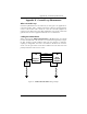
System Installation
The OMG-CONV-485-ISO can be connected to any existing RS-232 port. A cable
such as the CA-177 can be used to attach the OMG-CONV-485-ISO DB-25F to
the PC’s DB-9M connector.
1. Locate an existing RS-232 COM: port and connect the OMG-CONV-485-ISO.
2. With the OMG-CONV-485-ISO case open, configure dip switches SW1 and
SW2 for your application.
3. Connect the wiring to your external device via the provided 6-position screw
terminal. The signals are labeled on the board’s silk screen. From the
included hardware, select the strain relief clamp that best fits your cable.
4. Make sure all connections are secure and that strain relief is correctly
installed.
5. Close the OMG-CONV-485-ISO case and connect the included AC adaptor.
6. If the OMG-CONV-485-ISO is in RS-422 mode, the EN led should now be on
since the transmitter is always enabled.
Installation is complete.
Please Note:
On power-up, the OMG-CONV-485-ISO scans the Mode Select dip switch (SW1)
one time to determine the communication mode and then branches to the
selected control logic. No attempt is made to periodically check the switch for a
mode change. This is done for two reasons. First, our experience shows that a
device such as this is configured for the required application and the mode is not
changed after this. Due to this reason, the product is not burdened with the
overhead of always checking this switch. At higher baud rates this becomes
especially critical due to the speed of the onboard microcontroller. The utmost
priority is given to sampling the incoming data.
What this means?
If the OMG-CONV-485-ISO has been configured for a particular mode, and for
some reason it has become necessary to change the communication mode,
remove power, reconfigure the Mode Select dip switch (SW1) for the new mode,
and reapply power.