
user manual

Page 7
h) Install pivot mounting bracket and mount junction box on the bracket. Insert
pipe/sensor assembly through the bracket to the desired position. Tighten pipe
locking screw.
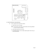
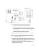
3.6 Sensor Installation, Submersion Mounting
3.6.1 a) Refer to diagram below and proceed as follows:
b) Route sensor cable through pipe and fasten sensor to pipe. The use of thread
sealant (Teflon tape) on all mounting hardware and sensor threads is
recommended to avoid leaks.
CAUTION: Do not remove measuring cell cartridge from hermetically sealed
package until it is to be used in step b). (Membrane will dry out and
damage measuring cell).
c) Install measuring cell cartridge. Unfasten union nut from sensor and make sure
to remove any moisture from cavity area and brass contact strips. Insert
cartridge in its correctly keyed position. Fasten union tightly so the O-ring
compresses to create an effective water-tight seal.
d) Mount the junction box within reach of the sensor cable.
e) Calibrate system in accordance with the procedure described in Section 5.3
before placing sensor into operation.
3.6.2 The terminal strip on the power supply board at the back of the instrument is
labeled for power supply, relay outputs and analog outputs. Connect wiring in
accordance with this labeling. CAUTION: Connecting the line voltage power
supply to incorrect terminals may cause serious damage.
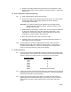
3.7 Probe Connections
3.7.1 The interconnect cable as supplied will normally be connected to the sensor cable
in the junction box. If this is not the case, connect the six wires and the shield of the
extension cable to the numbered wires in the junction box as shown below:
Extension Cable
Junction Box
Blue 1
Red 2
Black 3
Green 4
White 5
Yellow 6
Shield Unnumbered (Green/Yellow)
3.7.2 Connect the six wires of the interconnect cable to the terminal strip on the swing-out
board being sure to match colors as printed on the board. Connect the shield to the
terminal post located above the terminal strip.
3.7.3 Running the sensor and interconnect cable in 1/2” metal conduit for protection
against moisture and mechanical damage is recommended. Do not run power or
control wiring in the same conduit (“electrical noise” may interfere with sensor
signal).