
User's Manual


7 ELECTRONICS AND INTERFACING
This brief introduction to the electronics most often needed by digital I/O board users
covers a few key concepts.
IMPORTANT NOTE
WHENEVER AN 82C55 IS POWERED-ON OR RESET, ALL
PINS ARE SET TO HIGH-IMPEDANCE INPUT. FOLLOWING
STANDARD TTL FUNCTIONALITY, THESE INPUTS WILL
TYPICALLY FLOAT HIGH, AND MAY HAVE ENOUGH
DRIVE CURRENT TO TURN ON EXTERNAL DEVICES.
The implications of this is that if you have output devices such as solid state relays,
they may be switched on whenever the computer is powered on or reset. To prevent
unwanted switching and to drive all outputs to a known state after power on or reset,
pull all pins either high or low through a 2.2 K resistor.
7.1 PULL UP & PULL DOWN RESISTORS
Whenever the board is powered on or reset, the control register is set to a known
state. That state is all ports go to the input state.
The nature of the input means it will typically float high. However, depending on the
drive requirements of the device you are driving, they may float up or down. Which
way they float is dependent on the characteristics of the circuit and the electrical
environment; and may be unpredictable. This is why it often appears that the board
outputs have gone 'high' after power up. The result is that the controlled device gets
turned on. That is why you need pull up/down resistors.
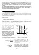
Shown in Figure 7-1 is an 82C55 digital
output with a pull-up resistor attached.
The pull-up resistor provides a reference
to +5V. The value of 2.2K ohms requires
only 2.3 mA of drive current.
If the board is reset and enters high
impedance input, the line is pulled high.
At that point, both the board AND the
device being controlled will sense a high
signal
Figure 7-1. Pull-up Resistor
.
20