
User's Manual


The most convenient way to use solid state relays and a PCI-DIO96 board is to use a
Solid State Relay Rack. An SSR Rack is a circuit board with input buffer amplifiers
that are powerful enough to switch the SSRs. The buffer amplifiers and SSRs are
socketed.
The standard buffer amplifiers are inverting types, meaning that a low input from a
DIO 82C55 outputs a high to the SSR which turns it on (“closes” the SSR output). If
desired, non-inverting amplifiers can be specified.
7.3 VOLTAGE DIVIDERS
If you wish to measure a signal that varies over a range greater than the input range
of a digital input, use a voltage divider to drop the voltage of the input signal to the
level the digital input can measure.
Ohm's law states:
Voltage = Current * Resistance
Thus, any variation in the voltage drop for the circuit as a whole will have a
proportional variation in all the voltage drops in the circuit.
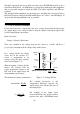
In a voltage divider, the voltage
across one of the resistors in a
circuit is proportional to the
voltage across the total resistance
in the circuit (Figure 7-2).
When designing a voltage divider,
choose two resistors with the
proper proportions relative to the
full scale of the digital input and
the maximum signal voltage.
The formula for voltage attenuation is: Figure 7-2. Voltage Divider
For example, if the signal varies
between 0 and 10 volts, and you wish to
measure that with a PCI-DIO96 board
2 = 10K+10K
10K
The variable Attenuation is the
proportional difference between the
signal voltage max and the full scale of
the analog input.
Attenuation = R1+R2
R2
22
Signal
High
Signal
Volts
Signal
Low
Vin
R1
R2
V1
V2
Vout
Board
Input
Ground
SIMPLE VOLTAGE DIVIDER - Vin = R1+R2
Vout R2