
User's Manual


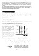


For a given attenuation, pick a handy
resistor and call it R2, then use this
formula to calculate R1.
R1=(A-1)*R2
with a full scale range of 0 to 5 volts,
the Attenuation is 2:1, or just 2.
Digital inputs can readily use voltage dividers. For example, if you wish to measure a
digital signal that is at 0 volts when off and 24 volts when on, you cannot connect
that directly to the PCI-DIO96 digital inputs. The voltage must be dropped to 5 volts
max when on. The Attenuation is 24:5 or 4.8. Use the equation above to find an
appropriate R1 if R2 is 1K. Remember that a TTL input is 'on' when the input
voltage is greater than 2.5 volts.
IMPORTANT NOTE
The resistors, R1 and R2, are going to dissipate all the power in
the divider circuit according to the equation Current = Voltage /
Resistance. The higher the value of the resistance (R1 + R2) the
less power dissipated by the divider circuit. Here is a simple rule:
For attenuation of 5:1 or less, no resistor should be < 10K.
For attenuation of greater than 5:1, no resistor should be < 1K.
23