&E RG-2500 Series a Tipping Bucket Rain Gauge 03-I 8 Operator% ManMal
Servicing USA and Canada: Call OMEGA Toll Free Canada USA One OmegaDrive, Box 4047 Stamford, CT 06907-0047 Telephone: (203) 359-1660 FAX: (203) 359-7700 976 Bergar Lava1 (Quebec)H7L5Al Telephone: (514) 856-6928 FAX: (514) 856-6886 Sales Service: l-800-826-6342/ l-BOO-TC-OMEGASM Customer Service: l-800-622-2378/ l-BOO-622-BESTSM Engineering Service: l-800-872-9436/ l-BOO-USA-WHENSM TELEX: 996404 EASYLINK: 62968934 CABLE: OMEGA Servicing Europe: United Kingdom Sales and Distribution Center 25 Swannington R
Y i
Unpacking Instructions Remove the Packing List and verify that you have received all equipment, including the following (quantities in parentheses): RG-2500 Tipping Bucket Rain Gauge (1) Operator’s Manual (1) If you have any questions about the shipment, please call the OMEGA Customer Service Department. When you receive the shipment, inspect the container and equipment for signs of damage. Note any evidence of rough handling in transit. Immediately report any damage to the shipping agent.
Y
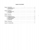
TABLE OF CONTENTS 1. Chapter 1 Introduction ......................................... 1.1 General Description ................... ‘ ................. 1 .1 1.2 Specifications....................................... Chapter 2 Installation .......................................... 2 2.1 Site Requirements ..................................... 2 2.2 Installation.......................................... 2 Chapter 3 Operation . . . . . . . . . . . . . . , . . . . . . . . . . . . . . . . . . . , , . . . . . . .
. Chapter 1: Introduction 1.1 General Description The RG-2500 Series consists of two high quality rain gauges, Models RG-2500RGand 2500-12. Model RG-2500 features a standard eight-inch diameter orifice, while the Model RG-2500-12 has a twelve-inch diameter orifice. Both gauges have been designed with high grade materials and have been built to provide years of trouble-free operation.
Chapter 2: Installation 2.1 Site Requirements The location of the rain gauge is very important to the successful operation of the instrument. The most accurate measurements are made in relatively sheltered areas protected from gusting and turbulent winds. Openings in orchards or a grove of trees offer the best exposure for the rain gauge. Fences and other structures can help serve as a wind break as long as they are not too tall.
The leveling knobs located above the mounting feet are secured using allen head set screws. These set screws must be loosened before the knobs can be moved. The set screws are accessible from the sides of the base. Re-tighten the set screws after leveling the gauge to help ensure that the level adjustment will not shift due to loose screws. The gauge may be installed with the outer cover on or with it removed. Three screws hold the outer cover in place. Take out these three screws to remove the cover.
Allow a measured amount of water to flow into the gauge at a specified rate. Refer to the table shown below. The tipping bucket should begin tipping and will give the number of tips calculated. The tips may be counted by listening to the bucket assembly and manually tabulating the count or by using the electronic monitoring equipment that is to be connected to the rain gauge during its normal operation.
4.4 Adjustments Should the calibration of the rain gauge appear to be incorrect and in need of adjustment, change the heights of the two calibration posts adjustment screws. To change the screw heights, loosen the nut on the top of the post that locks the screw into place. Rotate each screw by a small amount only and recheck the calibration for the new screw positions. Empty all water from the buckets but do not dry off the buckets.
by observing the data of the monitoring equipmen normally connected to the rain gauge. Manually move the bucket assembly and look for he switch closure. ge, replace the outer cover and funnel and Upon completion of testing and cleaning of the1ga recheck the level of the gauge using a carpenter ’s level across the top of the gauge. Adjust the leveling knobs at the mounting feet if the level is out of adjustment.
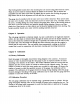
-- r Z-PI N TERMINAL BLOCK MAGNETIC SWITCH 25 FT CABLE MODEL 330-022 ( TYP IC A L) ( NORMALLY 0 DIODE __ _ __ OPEN) ------- -- 2-PI N TB RED &w DIODE * SWITCH BLK IL7 -0 BLK MAGNET N.O. 27 VD C MAXIMUM 3 WATT S 0.25A @ 175 VD MAXIMU M C TYPICAL CLOSURE TIME 0.1 SECON D NOTES: 1. TYPICAL OF BOTH HEATED AND UNHEATED RAIN GAUGES .
CASE GROUND /ib 4-PI N TERMINAL BLOC K 10 FUSE 5 AM P SLO BLO 25 FT POWER CORD 18 AWG, SVT - 34 OHMS FIRE ROD HEATER 400 W @ 115 VA C WARN’.ING 115 VAC WILL BE ALIVE ON THE 4-PI N TERMINAL BLOCK WHENEVER THE POWE R CORD IS PLUGGED INTO A POWER OUTLET . T!iE RAI N TERMINALS ARE EXPOSED INSIDE GAUGE.
8.0” ------I MOUNTING FEET PAT WTH LEVELER L(oo. \ BY 0.
0. ..‘. -. .- 2C 5” MOUNTING FEET PAT + 2.0” t MOUNTING FOOT WlTH LEVELER uoo.
a a I=
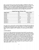
RAIN GAGE FUNNEL INNER FUNNEL 7 CALIBRATION POST SCREW & ADJUSTMENT 2 PIN SIGNAL f- TERMINAL BLOCK TIPPING BUCKET \ SIGNAL OUTPUT CONTACT CLOSURE COLLECTION TUBE FOOJI~JE MTH LEVELER 12 INCH RAIN GAGE BASE ASSEMBL I Y 1, OAIE
,/ THERMOS ‘TAT % RAIN GAGE FUNNE L\ d_ BOTTOM VIEW SIDE VIEW (WIRING OMITTED) W lT H LE VIEW OF MAGNET SIDE M LER RAIN GAGE BASE ASSEMBLY E NOTES - 1. 4 PIN TERMINAL BLOCK IS POSITIONED BEHIND HEATER 2. OUTER COVER NOT SHOWN. ’ nn . 1 UOD.
MOUNTING BOLT ASSEMBLY DETAIL PART NUMBEfiS RAI 72270101 72341501 7231750 2 5/16 HEX NUT 5/16 LOCK WASHER 5/16 FLAT WASHER g 7231750 5/16 FLAT WASHER v 2 72270101 5/16 HEX NUT 72270101 5/16 HEX NUT & LOC HEIG LOC 7250000 0 5/16 THREADED ROD 7231760 2 3/8 FLAT WASHER & ANC 5/16 HEX NUT & A 72270101 I FOR INSTALLATIONS USING A 24” ALTER ST WIND SCREEN THIS HEIGHT MUST BE ADJUSTED SO THAT THE TOP EDGE OF THE RAIN GAGE IS WITHIN 1 INCH OF THE TOP EDGE OF THE WIND SCREEN LEAVES.
MOUNTING BOLT ASSEMBLY DETAIL PART NUMBERS c ~ 20.75” 12 INCH RAIN GAGE I 7227010 1 7234150 1 7231750 2 7231750 2 5/16 HEX NUT 5/16 LOCK WASHER 5j16 FLAT WASHER @ & 5/16 FLAT WASHER F 7227010 1 5/16 HEX NU T 7227010 1 5/16 HEX NUT &I RAIN LOC HEIG LOC 7250000 0 5/16 THREADED ROD 7231760 2 3/8 FLAT WASHER & ANC 5/16 HEX NUT & ANC 7227010 1 I TYPICAL OF THREE EAC ! 15.
I /-- \\ I\\ I’,\ \ I I
1’1 S I LVER TAPE THERMOSTAT BRACKET (SHOWN IN INVERTED 00 :: INSULATING FOIL 25 - x11" i POUTION) 42 i \ 1 2 - x11” C FIREROD HEATE R THERMOSTAT HEAT S I NK TUBE CLAMP PLUG -+ SOCKET W ARN I NG LABEL DRAWING NOT TO SCALE \
PARTS LIST TIPPING BUCKET RAIN GAUGE MODEL RG-2500 8 INCH ORIFICE, 0.
Y 16
WARRANTY OMEGA warrants this unit to be free of defects in materials and workmanship and to give satisfactory service for a period of 13 months from date of purchase. OMEGA Warranty adds an additional one (1) month grace period to the normal one (1) year product warranty to cover handling and shipping time. This ensures that OMEGA ’s customers receive maximum coverage on each product. If the unit should malfunction, it must be returned to the factory for evaluation.
Where Do I Find Everything I Need for Proce !ss Measurement and Control? OMEGA...