
Air Compressor User Manual

UNPACKING
Remove the Packing List and verify that you have received all equipment. If
you have any questions about the shipment, please call the OMEGA
Customer Service Department at 1-800-622-2378 or (203) 359-1660. When
you receive the shipment, inspect the container and equipment for any signs
of damage. Note any evidence of rough handling in transit. Immediately
report any damage to the shipping agent.
NOTE
The carrier will not honor any claims unless all shipping material is saved for
their examination. After examining and removing contents, save packaging
material and carton in the event reshipment is necessary.
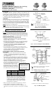
Fig. 2. Connection Diagram: Model SBG41705
Hazardous Location
Note: For 120V application, only one fuse is
required in the ungrounded circuit of the input line.
Fig. 1. Connection Diagram
(All Models Except SBG41705)
Note: All intrinsically safe wiring must be segregated
from non-intrinsically safe wiring.
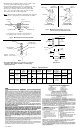
Fig. 3. Multiple units grouped on a common,
earth-grounded mounting plate.
Important: Read carefully and completely before
installing or connecting the solid-state relays.
• Whenever possible, the actual measured parameters should be
used in making the determination of allowable length.
• Shielded cable is not required, but if used in the application, the
shield must be returned to ground, the same point at mounting
tab.
GROUP
A & B
C
D
CAPACITANCE
0.1 µF
0.2 µF
0.3 µF
INDUCTANCE
3 mH
10mH
20mH
Example: Typical values of capacitance for a twisted
pair of copper wires is between 20 and 60 pF per foot.
Using the maximum value of 60pF/ft, Groups A & B
could have a run of 1500+ feet with safety. Inductance
of a typical twisted pair is between 0.10 and 0.20 µH/
ft, thus making a cable run in this example essentially
determined by the capacitance.
The OMEGA
®
SBG22445, SBG25872, SBG25873 and SBG41705 Solid-
State Relays are used as "intrinsically safe switching circuits in hazardous
locations, with non-voltage- producing sensors. When installed in accor-
dance with this manual, these field sensors are suitable for Class I, Division
1, 2, Groups A, B, C and D, and Class II, Division 2, Groups E, F and G as
defined by Article 500 of the National Electric Code.
DESCRIPTION
SBG22445, SBG25872, SBG25873 (Non-Latching),
SBG41705 (Latching) Solid-State Relays
for Intrinsic Safety Use
Instruction Sheet M1773/0794
*(Lockwashers to be internal or external tooth type)
Fig. 4. Unit Mounting Detail
ASSOCIATED EQUIPMENT
Caution: The intrinsically safe relays can be installed in panel assem-
blies in Class I, Div.2, Groups A, B, C and D or in a non-hazardous
location. Only the sensor's terminals provide an intrinsically safe switch
circuit (Fig. 1, 2). (Exia) means associated equipment "Appareilage
connexe", located in safe area.
MOUNTING AND ENCLOSURE CONSIDERATION
• Field wiring of intrinsically safe circuits is to be segregated from
non-intrinsically safe wiring by use of suitable barriers, separate
wireways or trays (see Fig. 3).
• Intrinsically safe and non-intrinsically safe connection points should
be located sufficiently apart to prevent any possibility of bypassing
or miswiring during installation or servicing of equipment.
• The enclosure shall contain a cautionary statement as follows:
"CAUTION: ANY SUBSTITUTION OF COMPONENTS MAY
IMPAIR INTRINSIC SAFETY".
• The mounting plate must be grounded to ensure intrinsic safety.
Resistance between the plate and earth ground should be less than
one ohm. (See Figs. 4 and 5 for recommended selection of
grounding hardware and refer to Article 250 of the National
Electrical Code for methods and practice.)
INSTALLATION OF SENSOR SWITCH AND ASSOCIATED
FIELD WIRING
• The nature of the sensor switch must be that it is a non-voltage-
producing, essentially resistive termination or other device
specifically examined and approved for use with the intrinsically
safe solid-state relay.
• The conductors of the intrinsically safe circuit should be sealed in a
rigid metal conduit at the point where the wiring enters the hazardous
area. The wiring and sensor switch should be such that conductive
dusts in the hazardous area will not close the circuit.
• Hazardous area field wiring will store energy due to distributed
capacitance and inductance in proportion to its length. It is
therefore recommended that the characteristics of the cable be
known and judged against the length of
run and atmosphere of exposure. The
following chart is presented as a guideline
in determining the limits of reactance for
signal loops in the hazardous area wiring
for the intrinsically safe solid-state relays.
WARNING
Product must be maintained
and installed in strict accor-
dance with the National Elec-
trical Code. Failure to observe
this warning could result in
serious injuries or damages.
Input
VAC
(EXIA)
Load
Fuse F1
Fuse
F1
Non-Hazardous
Location
Hazardous Location
Sensor Switch
Sensor Switch
LOAD
VAC
AC
Load
Latching Solid-State
Relay SBG41705
On
C
Off
Non-Hazardous
Location
Earth
Ground
(2 Places)
Common
Earth-
Grounded
Mounting
Plate
Intrinsically
Safe Wiring
To Sensors
Non-Intrinsically
Safe Wiring
Multiple
Units
Resistance to ground must be from bracket to
earthing member to insure integrity of system.
(Must be below one ohm.)
Mounting
Plate
#10
Nut
Intrinsically Safe
Solid-State Relays
#10 Screw
#10 Lockwasher*
#10 Lockwasher*