LOW-INTENSITY INFRARED HEATING SYSTEMS Omega II ® Pre Engineered Packages Products by: COMBUSTION RESEARCH CORPORATION SUBMITTAL DATA PROJECT: REVISED – March 25, 2006 submitom.
Specifications for Omega II® UNITARY P.E.P. SYSTEMS PART 1 - GENERAL It is the intent of this specification to identify design requirements and minimum standards for the quality, construction, delivery, installation, and operation of the low intensity, vacuum vented, gas fired infrared heating equipment. Minor variations, in accordance with standard practice, shall be indicated on the shop drawings and submitted for approval. 1.1 - CODES AND STANDARDS 1.1.
PART 2 - PRODUCT 2.1 - BURNER 2.1.1 Burner shall be capable of firing at 40,000 BTU/hr (11.72 kW/hr) up to and including 100,000 BTU/hr (29.3 kW/hr) at 5,000 BTU/hr (1.46 kW/hr) increments with natural gas or LP gas. 2.1.2 Burner power requirements 115 Volt, 60 Hz AC, 1.8 A. 2.1.3 Burner shall include the following features: a) Fitted with a 4" (102 mm) diameter combustion air inlet with a fixed combustion air-metering orifice.
2.3.5 Elbows and tube coupler to be made of min. 18 gauge (1.32 mm) aluminized steel, swaged at both ends so as to fit into 3.5" (89 mm) spiral tube. 2.3.6 Reflectors to be made of minimum 0.025" (0.635 mm) bright stainless steel. 2.3.7 Tubing and reflector hangers to be made of 0.25" (6.35 mm) Dia. Zinc plated CRS. 2.3.8 All joints to be sealed and mechanically fastened with self drilling and tapping screws. 2.3.9 All radiant tubing to be continuously covered by the reflector, i.e.
TECHNICAL DATA MANIFOLD GAS PRESSURE GAS INLET PRESSURE Natural Gas: 3.5" W.C. LP Gas: 10.0" W.C. ½" NPT Gas Connector Natural Gas: LP Gas ELECTRICAL RATING ALTITUDE 115 VAC, 60 Hz, 1.8 Amp Systems 0S922 thru 0S910 (40k thru 100k Btu/hr input) 0- 4,500 ft. (0 – 1370 m) No derating required. 6.0" W.C. Min. 11.0” W.C. Min. 14.0" W.C. Max. 14.0” W.C. Max. Systems 0S926 thru 0S945 (105k through 200k input) 0 - 2,000 Ft. (0 - 610m) No derating required. 2,000 - 4,500 Ft.
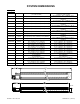
SYSTEM DIMENSIONS 3.5" Omega II® BURNER P.N. BTU/Hr INPUT A ("U" TUBE SYSTEM) B (STRAIGHT TUBE SYSTEM) 0S922.NG/LP 40,000 5'-0" (1524mm)/10'-0" (3048mm) 10'-0" (3048mm)/19'-8" (6020mm) 0S921.NG/LP 45,000 5'-0" (1524mm)/10'-0" (3048mm) 10'-0" (3048mm)/19'-8" (6020mm) 0S920.NG/LP 50,000 10'-0" (3048mm) / 14'-8" (4496mm) 19'-8" (6020mm) / 29'-10" (9093mm) 0S919.NG/LP 55,000 10'-0" (3048mm) / 14'-8" (4496mm) 19'-8" (6020mm) / 29'-10" (9093mm) 0S918.
SYSTEM DIMENSIONS 4" Omega II® BURNER P.N. BTU/Hr INPUT A ("U" TUBE SYSTEM) 0S926.NG/LP 105,000 14'-8" (4496mm) / 19'-11" (6071mm) / 24'-9" (7544mm) 0S927.NG/LP 110,000 14'-8" (4496mm) / 19'-11" (6071mm) / 24'-9" (7544mm) 0S928.NG/LP 115,000 14'-8" (4496mm) / 19'-11" (6071mm) / 24'-9" (7544mm) 0S929.NG/LP 120,000 19'-11" (6071mm) / 24'-9" (7544mm) / 29'-9" (9068mm) 0S930.NG/LP 125,000 19'-11" (6071mm) / 24'-9" (7544mm) / 29'-9" (9068mm) 0S931.
EXHAUST METHODS COMMON VENTING 1. The total stack length from the OMEGA II exhaust to the point where it terminates should be a minimum of three feet (3') and a maximum of twenty feet (20'). It is recommended that any portion of flue pipe that passes through the roof or wall be a double wall vent, 'B' vent is recommended (check local codes) . 2. Horizontal runs to vertical vent should never exceed 75% of the vertical height of the vent stack. Refer to ANSI Z223.
COMBUSTION RESEARCH CORPORATION Part No. 0317.00, Gas Connector Stainless Steel Gas Connector with Manual Valve STAINLESS STEEL GAS CONNECTOR INSTALLATION & CHECKOUT INSTALLATION Install the stainless gas connector as outlined in the owner's manual. The stainless steel gas connector is to be installed with the manual gas valve on the upstream side. Stainless steel flex construction - Corrosion resistance. No-NeckTM Design - Added safety. Manual connector valve included.
COMBUSTION RESEARCH CORPORATION HEAT TREATED ALUMINIZED 409 STAINLESS STEEL COMBUSTION TUBE Burner Combustion Tube 16 Ga. Heat Treated Aluminized 409 StainlessSteel INSTALLATION & CHECKOUT Installation Aluminized 409 StainlessSteel Construction – Heat treated Used With Omega II® Radiant Tube System Corrosion Resistant SPECIFICATIONS CRC Part No.: 0404.SS.16.HT - 4” diameter radiant tube Wt. – 26.0 lbs. (11.8 kg) 0304.SS.16.HT - 3.5” diameter radiant tube Wt. – 23.5 lbs. (10.6 kg) Install 16 Ga.
COMBUSTION RESEARCH CORPORATION HEAT TREATED ALUMINIZED 409 STAINLESS STEEL RADIANT TUBE Heat treated Aluminized 409 Stainless Steel Spiral Construction 9’-9” Long Sections Used With Omega II® Radiant Tube System Patented, Strong, Low Mass Tube (Min. 22 Ga.) Corrosion Resistant SPECIFICATIONS CRC Part No.: 0404.SS.HT - 4” diameter radiant tube Wt. – 13.0 lbs. (5.9 kg) 0304.SS.HT - 3.5” diameter radiant tube Wt. – 13.0 lbs. (5.
COMBUSTION RESEARCH CORPORATION Part No. 0360.02, Reflector Stainless Steel Reflector ALUMINUM REFLECTOR INSTALLATION & CHECKOUT INSTALLATION Install reflectors over radiant tubes as shown on shop drawing. Note, secure reflectors together at each straight run allowing for one unsecured joint for expansion - Refer to the owner's manual for installation guidance.
COMBUSTION RESEARCH CORPORATION Part No. 0306.P1.SS, Elbow Package SS Reflector Elbow & 3.5”, 90° Tube Elbow ELBOW PACKAGE INSTALLATION & CHECKOUT INSTALLATION Install radiant tube elbow and reflector elbow as shown on shop drawing. Note, secure tube elbow to radiant tubes with self drilling and taping screws and secure reflector elbow to the adjacent reflectors with the self drilling and tapping sheet metal screws - Refer to the owner's manual for installation guidance.
COMBUSTION RESEARCH CORPORATION Part No. 0406.P1.SS, Elbow Package SS Reflector Elbow & 4.0”, 90° Tube Elbow ELBOW PACKAGE INSTALLATION & CHECKOUT INSTALLATION Install radiant tube elbow and reflector elbow as shown on shop drawing. Note, secure tube elbow to radiant tubes with self drilling and taping screws and secure reflector elbow to the adjacent reflectors with the self drilling and tapping sheet metal screws - Refer to the owner's manual for installation guidance.
COMBUSTION RESEARCH CORPORATION Radiant Tube Coupler Aluminized Steel Radiant Tube Coupler ALUMINIZED STEEL TUBE COUPLER INSTALLATION & CHECKOUT INSTALLATION Install coupler as shown on shop drawing. Note couplers are designed to fit inside the spiral radiant tube. Apply sealer to internal surface of radiant tube before inserting coupler. Secure with three self drilling and taping screws on each swaged end. Refer to the owner's manual for installation guidance.
COMBUSTION RESEARCH CORPORATION Part No. 5484.00 Thermostat Line Voltage Wall Thermostat THERMOSTAT FEATURES 70 Thermostat connects to standard 2" x 4" electrical single gang box. Single pole. Underwriter's Laboratories (UL) listed for the U.S. & Canada. Vertical mounting on 2" x 4" single gang outlet box. Color-coded lead wire connections. Dial with temperature in Fahrenheit, 50° F to 90° F temperature range. Multiple burners can be controlled by one thermostat.
COMBUSTION RESEARCH CORPORATION Part No. 5487.00 Thermostat NEMA 4X, Line Voltage Wall Thermostat THERMOSTAT FEATURES N.E.M./A. 4X enclosure complies with N.E.C Article 547 when used with appropriate watertight connections Rugged weather resistant enclosure made of corrosion resistant materials. Low mass, high surface area of stainless steel coiled sensor provides rapid response to temperature change.
COMBUSTION RESEARCH CORPORATION Part No. 5490.02 Thermostat 120 Volt Programmable Wall Thermostat THERMOSTAT FEATURES Thermostat t Thermostat connects to standard 2" x 4" electrical single gang box. Weekday/Weekend Programmable thermostat Four periods per day Temporary temperature override Vacation Hold Vertical mounting on 2" x 4" single gang outlet box. Fahrenheit or Celsius readings With temperature in Fahrenheit, 45° F to 90° F temperature range.
COMBUSTION RESEARCH CORPORATION Part No. 5490.01 Thermostat 24 Volt Programmable Wall Thermostat THERMOSTAT FEATURES Thermostat connects to standard 2" x 4" electrical single gang box. Weekday/Weekend Programmable thermostat Four periods per day Horizontal mounting on 2" x 4" single gang outlet box. Fahrenheit or Celsius readings With temperature in Fahrenheit, 45° F to 90° F temperature range. Energy Star® compliant SPECIFICATIONS INSTALLATION & CHECKOUT CRC Part No.: 5490.
COMBUSTION RESEARCH CORPORATION SWITCHING REALY Control center for operating 120V burner assemblies with a 24V thermostat. Standard mounting on 4 x 4 junction box. SPECIFICATIONS CRC Part No.: 5541.03 – Switching Relay (Wt. – 2.75 Lbs., 1.25 kg) Dimensions: 4" (102 mm) x 4" (102mm) x 3.5” (89mm) High Mounting: Part No. 5541.03 Switching Relay Switching Relay, Control Center Contact Ratings at 120Vac Full Load: 13.8 amp Locked Rotor: 82.
COMBUSTION RESEARCH CORPORATION Part No. 0314.00, Fresh Air Inlet Assembly 4” Fresh Air Inlet, Flex & Clamps FRESH AIR INLET ASSEMBLY INSTALLATION & CHECKOUT INSTALLATION: Install fresh air assembly as shown on shop drawing. Apply silicone sealer to external surface that mounts against wall. Secure to wall with three screws. Refer to the owner's manual for installation guidance.
COMBUSTION RESEARCH CORPORATION Part No. 1811.VT.400 4” Round Vent Cap SIDE WALL VENT TERMINAL INSTALLATION & CHECKOUT INSTALLATION Install the vent cap as shown in the Owners' Manual and shop drawings. Observe any clearance to combustibles and applicable installation codes. High Wind Vent Cap 4” Diameter (“B” Vent) Inlet Aluminum Construction Corrosion resistant SPECIFICATIONS CRC Part No.: CHECKOUT Make sure that vent terminal is securely fastened to venting pipe (supplied by installer).
COMBUSTION RESEARCH CORPORATION Part No. 1811.VT.600 6” Round Vent Cap SIDE WALL VENT TERMINAL INSTALLATION & CHECKOUT INSTALLATION Install the vent cap as shown in the Owners' Manual and shop drawings. Observe any clearance to combustibles and applicable installation codes. High Wind Vent Cap 6” Diameter (“B” Vent) Inlet Aluminum Construction Corrosion resistant SPECIFICATIONS CRC Part No.: CHECKOUT Make sure that vent terminal is securely fastened to venting pipe (supplied by installer).
COMBUSTION RESEARCH CORPORATION Part No. 1800.CS 5’ of Hanging Chain & “S” Hooks HANGING CHAIN & “S’ HOOKS INSTALLATION & CHECKOUT INSTALLATION Install chain and “S” hooks as shown in the Owners' Manual and shop drawings. Double Loop Hanging Chain – 5’ Long “S” hooks – Qty. two SPECIFICATIONS CHECKOUT Make sure that all “S” are crimped closed Install as outlined in the Owners' Manual and in accordance with applicable codes. CRC Part No.: 1800.CS (Wt. – 0.25 Lbs., 0.