
User Manual

Omega II
®
Installation, Operation & Maintenance
Page 22 Combustion Research Corporation
COMMON VENTING
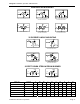
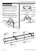
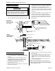
1. The total stack length from the OMEGA II
®
exhaust to
the point where it terminates should be a minimum of
three feet (3') and a maximum of twenty feet (20'). The
portion of flue pipe that passes through the roof (or attic
space) be a double wall vent - 'B' vent (check local
codes).
2. Horizontal runs to vertical vent should never exceed
75% of the vertical height of the vent stack. Open area
of common exhaust must equal the sum of the open
area of individual flue vents connected to it. Refer to
the ANSI Z223.1 (current standard) (same as bulletin
NFPA-54) for listing of various vent sizing for power
vented appliances. The minimum vent height and
diameter must comply with the above standard.
3. When exhausting more than one OMEGA II
®
heater into
a common stack the same thermostat must control all
associated heaters.
4. Connections to a common stack should be staggered so
as to avoid direct opposition between streams of
combustion gasses.
5. A 1" minimum clearance must be maintained around
vent when passing through a combustible roof.
6.
An approved Vent Cap should be used on all through
the roof applications. The National Fire Protection
Standards, NFPA Numbers 54 and 211, require that
unless an approved Vent Cap is used the vent must
extend at least two feet above the highest portion of a
building within ten feet.
All Joints in the flue should be sealed. Use General Electric
RTV 106 or Permatex Form-A-Gasket Red High
Temperature Silicone Adhesive Sealant.
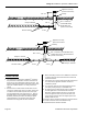
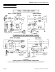
A
pproved Vent Cap
(Check Local Codes
Flashing
Min. 1" Clearance (Combustible Roof)
Min. 24"
Min. 6" Vent
Double Wall Vent For Roof Penetration
(Check Local Codes)
4" Vent
Roof
Omega II
®
Exhaust
A
ll Joints Sealed
4" Vent
Omega II
®
Exhaust
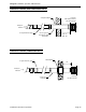
A
pproved Vent Cap
(Check Local Codes)
Flashing
Min. 1" Clearance
(
Combustible Roof
)
Min. 24"
Min. 4"
Double Wall Vent
(Check Local Codes)
4" Vent
Roof
Omega II Exhaust
A
ll Joints Sealed