
- OMEGA Desktop PC User's Manual
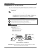


OMB-DaqBook User’s Manual
01-23-02 DaqBook Hardware 3-3
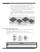
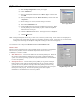
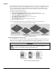
Front and Rear Panels Excluding DaqBook/260
The following illustrations show the relative locations of connectors, power switches, indicator LEDs, and
the expansion slot, as applicable. DaqBook/260 is treated separately in an upcoming section.
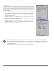
Reference Note:
DaqBook/260 users should refer to page 3-12 for information specific to that product.
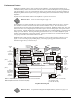
Front Panel of DaqBook/112/216
Rear Panel of DaqBook/112/216
P1 - ANALOG I/O
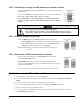
Front Panel of DaqBook/100/120/200
P1 - ANALOG I/O P2 - DIGITAL I/O P3 - FREQUENCY I/O
Rear Panel of DaqBook/100/120/200
DaqBook Controls and Connectors
Switch
POWER Depressing the “1” side of this rocker-arm switch turns the power on.
Connectors
POWER INPUT This DIN5 input connector accepts +7 to 20 VDC for the /100, /112, /120; +10 to
24 VDC for the /216; +9 to 18 VDC for the /200, /260.
TO PARALLEL PRINTER This port allows the computer to use any standard parallel printer in a
pass-through mode (DB25).
FROM PC PARALLEL
PORT
This port connects to the computer’s standard or enhanced parallel port (DB25).
P1 - ANALOG I/O Provides sixteen analog input channels, two analog output channels,
two 16-bit counter/timers, four TTL inputs and outputs, and various signals for
driving expansion cards (DB37).
P2 - DIGITAL I/O Provides three 8-bit TTL programmable I/O ports and external interrupt input
(DB37).
7P3 - FREQUENCY I/O Provides five 16-bit counters and sixteen high-speed digital inputs and external
interrupt input (DB37).
Indicators
POWER This LED lights when power is applied to the DaqBook and the power switch is in
the “1” (ON) position.
P1-P2-P3 ACTIVE This LED lights when the DaqBook is in an active state. This LED is off when
the DaqBook is disabled or in the printer-pass-through mode. P1, P2, and P3
are software accessible from the computer.
BUFFER OVERRUN This LED lights for a buffer overrun error. This occurs when A/D signals are
converted faster than the PC collects the data. Depending on the application,
this indication may not be an error.
A/D ACTIVE This LED lights during an A/D scan sequence. If the sequence has a low
number of steps and occurs infrequently, this indicator will only flash briefly.