User’s Guide Shop online at omega.com e-mail: info@omega.com For latest product manuals: omegamanual.
OMEGAnet ® Online Service omega.com Internet e-mail info@omega.com Servicing North America: U.S.A.: ISO 9001 Certified Canada: One Omega Drive, Box 4047 Stamford, CT 06907-0047 Tel: (203) 359-1660 FAX: (203) 359-7700 e-mail: info@omega.com 976 Bergar Laval (Quebec) H7L 5A1, Canada Tel: (514) 856-6928 FAX: (514) 856-6886 e-mail: info@omega.ca For immediate technical or application assistance: U.S.A.
Unpacking Instructions Notes n4
Unpacking Instructions Remove the Packing List and verify that you have received all equipment, including the following (quantities in parentheses): • OS530/OS520 Series Handheld Infrared Thermometer (1) • AA Size Lithium Batteries (4) • Soft Cover Carrying Case (1) • Analog Cable (1) • RS232 Cable (only for OS533E, OS534E, OS523E, OS524E) • CD Software (only for OS533E, OS534E, OS523E, OS524E) • Quick Start Manual (1) Accessories Model No.
ii
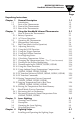
OS530E/OS520E Series Handheld Infrared Thermometer TABLE OF CONTENTS Page Unpacking Instructions Chapter 1 General Description 1.1 Introduction 1.2 Parts of the Thermometer 1.2.1 Front of the Thermometer 1.2.2 Rear of the Thermometer Chapter 2 Using the Handheld Infrared Thermometer 2.1 How to Power the Thermometer 2.1.1 Battery Operation 2.1.2 AC Power Operation 2.2 Operating the Thermometer 2.2.1 Measurement Techniques 2.3 Real Time Mode (Active Operation) 2.3.1 Adjusting Emissivity 2.3.
TABLE OF CONTENTS Chapter 5 5.1 5.2 5.3 5.4 Chapter 6 6.1 6.2 6.3 6.
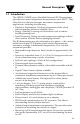
General Description 1 1.1 Introduction The OS530E/OS520E series Handheld Infrared (IR) Thermometers provide non-contact temperature measurements up to 4500°F. They offer effective solutions for many non-contact temperature applications, including the following: • Predictive Maintenance: Tracking temperature shifts which indicate pending failure in solenoid valves. • Energy Auditing: Locating wall insulation voids to reduce building heating costs.
1 General Description The thermometer is easy to use: • Units have standard “V” groove aiming sights. • Integral tripod mount permits hands-free operation, if necessary. • Temperature readings are switchable from °F to °C via the keypad. • Parameters, such as target material emissivity and alarm setpoints, can be set and remain in memory until reset. This instrument has a rugged and functional design, including: • Sealed keypad display. • Convenient trigger operation.
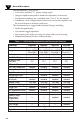
General Description Features Accuracy* Range Emissivity Display Resolution Backlit Dual Display Field of view Differential Temperature Min/Max Temperature Average Temperature High Alarm Low Alarm Audible Buzzer & Indicator Ambient Target Temp Compensation Analog Output RS232 Output Data Storage Built-in Laser sighting Trigger Lockstd Last Temperature Recall Thermocouple Input Distance Measurement Digital Camera 1 OS530HRE 3°F (1.7 °C) -22 to 250°F -30 to 121°C Adjustable 0.1°For 0.
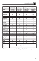
1 General Description Features Accuracy Range Emissivity Backlit Dual Display Distance to Spot Size Ratio Differential Temperature Min/Max Temperature Average Temperature High Alarm Low Alarm Audible Alarm & Indicator Ambient Target Temperature Compensation Analog Output RS-232 Output Thermocouple Input Data Storage Built-in Laser Sighting Trigger Lock Last Temperature Recall Distance Measurement Digital Camera OS523E** ±1% rdg 0 to 2500°F (-18 to 1371°C) adjustable standard varies** standard standard st
General Description 1 1.2 Parts of the Thermometer 1.2.1 Front of the Thermometer Digital/Video Camera (Optional) “V” Groove Lens Rubber Boot Built-in Distance Module (Optional) Display Rubber Boot Backlit LCD Distance Power Switch Trigger Battery Compartment Door Tripod Mount Wrist Strap Figure 1-1. OS530E/OS520E Series Handheld Infrared Thermometer Front View The display is shown in more detail in Figure 1-2 and described in Table 1-2. There are no user-serviceable parts in the thermometer.
1 General Description 1 OMEGASCOPE® 2 3 LCK ATC 10 HAL LOBAT LAL PRN °F °C 4 5 ® 9 Figure 1-2.
General Description 1 Figure 1-3 shows the various jacks for analog output, thermocouple input and the ac adapter to the thermometer. The figures also show the location of the Laser Power Switch, Dot-Circle Switch, and Laser Beam Aperture. More details are provided in Section 2.2.1.
1 General Description Notes 1-8
Using the Handheld Infrared Thermometer 2 2.1 How to Power the Thermometer 2.1.1 Battery Operation Invert the thermometer and install 4 fresh AA size batteries as shown in Figure 2-1. Make sure the batteries’ polarities are correct, the batteries are not put in backwards, and are of the same type. NOTE If the icon flashes, the batteries must be replaced with fresh batteries immediately. C F FU NC LO CK ® T BA °C LO °F L PRN HA K LAL LC C AT OM PE CO AS EG ® Figure 2-1.
2 Using the Handheld Infrared Thermometer 2.2 Operating the Thermometer 1a. (Without the Laser Sighting) -Aim the thermometer at the target to be measured. Use the “V” groove (shown in Figure 1-1) on top of the thermometer to align the target to the thermometer’s field of view. Look down the “V” groove with one eye only, in order to guarantee proper sighting. Pull and hold the trigger. 1b. (With the Laser Sighting) - Set the laser power switch to the ON position. Aim at the target and pull the trigger.
2 Using the Handheld Infrared Thermometer DISTANCE: SENSOR TO OBJECT (FT) SPOT DIA.* (IN) 0** 20" 2' 1' 3' 4' 5' 6' 7' 4.2" 8' 4.8" 3.6" 1.0" @ 0" to 20" 3.0" 2.4" 1.0" 1.0" 1.8" 1.2" D:S = 20:1 2.5 SPOT DIA.* (CM) 4.0 6.0 8.0 2.5cm @ 51cm 10.0 *SPOT DIAMETER MEASURED AT 90% ENERGY 40 80 120 12.2 160 200 244 DISTANCE: SENSOR TO OBJECT (CM) Figure 2-4 Field of View OS533E, OS530HRE ** Measurement distance is from the outside surface of the rubber boot.
2 Using the Handheld Infrared Thermometer SPOT DIA.* (IN) DISTANCE: SENSOR LENS TO OBJECT (in.) 0 6" 3" 9" 15" 12" 1.17" 0.9" .45" .39" .15" .78" SPOT DIA.* (MM) D:S = 40:1 3.9 11.5 22 9.9 19.9 29.9 *SPOT DIAMETER MEASURED AT 90% ENERGY 22.9 15.2 7.6 0 38.1 30.5 DISTANCE: SENSOR LENS TO OBJECT (cm.) Figure 2-6 Field of View OS53xE-CF SPOT DIA.* (IN) DISTANCE: SENSOR TO OBJECT (FT) 3' 0' 5' 10' 16' 2.9" 1.9" 0.9"@ 0 1.2" 1.0" 0.9" D:S = 60:1 SPOT DIA.
Using the Handheld Infrared Thermometer 2 SPOT DIA.* (IN) DISTANCE: SENSOR TO OBJECT (FT) 0’ 3’ 2’ 5’ 10’ .35"@ 24" 4.0" .8" .9" 21 22 16’ 7.0" 1.6" 42 101 181 SPOT DIA.* (MM) 9mm @ 610mm *SPOT DIAMETER MEASURED AT 90% ENERGY 0 .61 1.0 1.5 3.0 5.0 DISTANCE: SENSOR TO OBJECT (M) Figure 2-8 Field of View OS523E-3 SPOT DIA.* (IN) DISTANCE: SENSOR TO OBJECT (FT) 0' 16' 50' 82' 0.5"@ 0 8.7" 1.5" 0.9" 5.1" D:S = 110:1 SPOT DIA.
2 Using the Handheld Infrared Thermometer 3. The target temperature and emissivity are displayed on the LCD. Determine the emissivity of the target (refer to Appendix B). Press the key to increment the target emissivity. Press the C F key to decrement the target emissivity. 4. Press the LOCK key to lock the trigger. The icon will appear on the display. This allows the thermometer to operate continuously whether or not the trigger is pulled.
Using the Handheld Infrared Thermometer 2 • Static Surface Scan – Measures the temperature across a static surface: 1. Aim the thermometer at a starting point and pull the trigger. Press the LOCK key to lock the trigger. 2. If necessary, adjust the emissivity. 3. Slowly move the thermometer so that the line of sight sweeps across the surface. The thermometer measures the temperature at each point on the surface.
2 Using the Handheld Infrared Thermometer 1. 2. Mount the thermometer on a camera tripod and aim at the target. Connect the analog output of the thermometer to a strip chart recorder as shown in Figure 2-11. 3. Pull the trigger and press the 4. 5. If necessary, adjust the emissivity. The thermometer is now set up for unattended monitoring of temperature over time. You can also download the temperature to a Serial Printer or a PC for further analysis (Models OS533E, OS534E, OS523E, OS524E).
DISPLAY MODE: LOCK to... ––– Turn on/off Logging Set Data Transmission interval (Logging) Set Ambient Target temp Set Low Alarm set point Turn on LCD Back lite Change °F to °C Set High Alarm set point F to turn on/off LCD backlight to... Press C to change from °F to °C or feet to meter and vise versa Press or Set Emissivity Press C F Go to Enable/Disable LAL Enable/Disable ATC Enable/Disable PRN Enable/Disable HAL –––––– Reset Maximum, Minimum, Diff.
2 Using the Handheld Infrared Thermometer MODE DISPLAY DISPLAY LCK LCK LCK ☞ * FUNC MODE HAL ☞ FUNC ☞ FUNC (Models OS530LE, OS530HRE) LCK ☞ * * LCK FUNC (Model OS532E) LCK LCK ☞ * LAL FUNC ☞ LCK FUNC LCK ATC ☞ * FUNC ☞ LCK FUNC LCK PRN ☞ FUNC ☞ LCK * ☞ ☞ (Model OS533E) LCK FUNC ☞ LCK * FUNC FUNC (Models OS534E, OS523E, OS524E) on FUNC LCK ☞ FUNC Figure 2-13.
Using the Handheld Infrared Thermometer 2 2.3.1 Adjusting Emissivity °F Refer to Appendices B and C for information on emissivity. 1. Determine the emissivity of the target. 2. Aim at the target and pull the trigger. 3. If necessary, press the or press the C F key to increment the target emissivity key to decrement the target emissivity. NOTE The Emissivity Display Mode (E) appears every time the trigger is pulled regardless of how the Display Mode was previously set.
2 Using the Handheld Infrared Thermometer 2.3.4 Using the Distance Function CAUTION LCK • There should be a clean, open line of sight from the distance device to the target, otherwise an erroneous reading will result. • For accurate distance measurement readings, the surface must be hard, flat, and reflective to ultrasonic pulse. • Distance measurement can not be taken through glass, or off of soft and padded surfaces, or through smoke or fog.
Using the Handheld Infrared Thermometer The built-in version (-DM) is an integal part of the thermometer, and distance measurment is made using the thermometer's keypad. Go to the d_F or d_M display menu. There is a slide power switch on the side of the distance module housing. Make sure the power switch is ON. Pull the trigger for about 2 seconds, and the upper display will show the distance to the target either in Feet or Meter.
2 Using the Handheld Infrared Thermometer BEAM DIA.* (IN) DISTANCE METER TO OBJECT (FT) 3' 0' 5' 10' 16' 30.0" 18.0" 0.5"@ 0 10.0" 6.0" HH-DM ® DISTANCE MEASURING REFERENCE LINE D:S = 6.5:1 BEAM DIA.* (CM) 15 25 1.2 @ 0 46 76 0 1.0 1.5 3.0 5.0 DISTANCE METER TO OBJECT (M) Figure 2-17.
Using the Handheld Infrared Thermometer 2 2.3.5 Laser Sighting Status In the LSR display menu, the status of the laser sighting is shown either as Flashing (FLS) or continuous (on). Pressing the LOCK key will change the status from flashing to continuous and vise versa. There is a slide laser power switch on the left side of the thermometer's case. Set the power switch to ON position, and pull the trigger.
2 Using the Handheld Infrared Thermometer 2.3.7 Changing the Temperature from °F to °C (or vice versa) During the time the thermometer displays either d_F, d_M, MAX, MIN, dIF, AVG or thermocouple temperature, press the C F key to change all the temperatures from °F to °C or vice versa. 2.3.8 Turning on the Display Backlighting During the time that the thermometer displays either d_F, d_M, LSR, MAX, MIN, dIF, AVG, or TC temperatures, press the key to turn the display backlighting ON/OFF. 2.3.
Using the Handheld Infrared Thermometer 2 2.3.10 Using the Alarm Functions HAL °F The thermometer provides audible and visible alarm indications. • To set the high alarm value: 1. Pull the trigger. Then press and hold the FUNC key until the High Alarm Display Mode (HAL) appears. 2. Press the the 3. C F key to increment the high alarm value. Press key to decrement the high alarm value. Press the LOCK key to enable the high alarm function. The icon appears.
2 Using the Handheld Infrared Thermometer NOTE The high alarm setpoint does not change when the thermometer is turned off. However, when the batteries are replaced, it is reset to the default value as follows: OS530HRE: 250°F OS530LE, OS532E, OS533E: 1000°F OS534E: 1600°F OS523E: 2500°F OS524E: 4500°F • To set the low alarm value: (OS533E, OS534E, OS523E, OS524E): LAL °F 1. Pull the trigger. Then press and hold the FUNC key until the Low Alarm Display Mode (LAL) appears. 2. Press the the 3.
Using the Handheld Infrared Thermometer 2 2.3.11 Using Ambient Target Temperature Compensation (OS533E, OS534E, OS523E, OS524E) AT C °F Use the Ambient Target Temperature Compensation (AMB) Display Mode when high accuracy readings under both of these conditions are required: • The target has a low emissivity. • The ambient temperature around the target is much higher than the ambient temperature around the infrared thermometer. To set and activate the Ambient Target Temperature Compensation Mode: 1.
2 Using the Handheld Infrared Thermometer 8. AT C °F Press and hold the FUNC key until the Emissivity Display Mode (E) appears. 9. Change the emissivity to the proper value for the target being measured (refer to Section 2.3.1). 10. Aim at the target. The target temperature and emissivity are displayed on the LCD. 11.
Using the Handheld Infrared Thermometer 2 Sending temperature data to PC in Real Time: 1. From Windows Operation System, Go to Start Program Omega Infrared Temperature Measurement IRTM then click. 2. Check the RS232 connection between the infrared thermometer and the PC. Select your serial COM Port number from the Communication Port Setting menu on the menu bar. Turn on the infrared thermometer by pulling & locking the trigger. From the program screen, click the Start button.
2 Using the Handheld Infrared Thermometer NOTE The transmitted temperature data is the average temperature for the specified data transmission interval. The data transmission interval (PRN) can be set any where from 1 to 1999 seconds. You can save the data into a file by going into the File menu. Download Stored Temperature data to PC • Run the IRTM program.
Using the Handheld Infrared Thermometer 2 Menu Description File Save Data As... Save the collected temperature data in one of the formats: Excel File (.xls), Text File (.txt), Data File (.dat) Exit No Do you want to save your temperature data? Yes Cancel Exit the program without saving data Save the data then Exit the program Go back to Program View Show (Hide) Data File Show or Hide the Data Table on the screen. The data table shows the last 10 temperature data points.
2 Using the Handheld Infrared Thermometer Tool Stop Data Transmission to Change Parameters Stop data transmission to be able to change parameter settings like E, HAL, LAL, etc. Any change of parameter settings will reflect on the thermometer's display. When done with parameter settings, click the Start button to restart data transmission. Change Temperature Display between °F<-> °C You can change the temperature display from °F to °C or vise versa. It gets reflected on the thermometer's display as well.
Using the Handheld Infrared Thermometer 2 2.3.13 PC Interface Commands You can communicate directly from the PC to the infrared thermometer. Here are the Comm port settings and communication commands from the PC: Baud rate: 9600 Data: 8 Bits One Stop Bit No Parity All the PC commands to the infrared thermometer are case sensitive and terminates with a carriage return (CR). You can change parameter settings from the PC when data transmission is stopped.
2 Using the Handheld Infrared Thermometer String E:95; MAX:78; MIN:65; DIF:13; AVG:72; DIS:1144; HAL:900; TC:74; TEF:0; LAL:20; AMB:125; PRN:5; PRNF:1; IR:73; CF:0; FF:1; LF:0 End 2-26 Description Emissivity is 0.95 Maximum temperature is 78 Minimum temperature is 65 Differential temperature is 13 Average temperature is 72 Distance is 11.
Using the Handheld Infrared Thermometer 2 2.3.14 Storing Temperature Data on Command (OS534E, OS523E, OS524E) °F The thermometer can store up to 800 temperature data points on command. This data is stored in the non-volatile memory, so removing the batteries will not affect or erase this data. To store temperature data: 1. Aim at the target and pull the trigger and press the LOCK key to lock the trigger. The icon will appear on the display. 2.
2 Using the Handheld Infrared Thermometer 2.3.15 Logging Temperature Data in Real Time (OS523E, OS524E,OS534E) on LCK °F The thermometer can log temperature data in real time. The logged data is stored in the non-volatile memory, so removing the batteries will not affect or erase the data. The data is logged based on the data recording interval (PRN) which can be set anywhere from 1 to 1999 seconds. The thermometer can log up to 800 data points.
Using the Handheld Infrared Thermometer 2 2.3.16 Erasing the Temperature Data from Memory The user can erase all 800 temperature data points in memory at any time by using the following procedure: 1. Pull the trigger and press the LOCK key. The icon will appear. 2. Press the FUNC key until reaching the MEM or LOG disply mode. 3. Press the then LOCK keys in rapid sequence. The display shows ERASE on the top and it will beep to indicate that the stored data is erased.
2 Using the Handheld Infrared Thermometer 2.4 Recall Mode (Passive Operation) Definition: Recall Mode is the passive operational mode of the thermometer. In this mode, you may review the most recently stored temperature data and parameters. Start Sleep Mode Pull Trigger Display Turns Off Approx. 5 Seconds (Release Trigger) Press FUNC (Table 2-1) Real Time Mode (Active) Display Turns Off in Approx. 5 Seconds (No keys pressed) Recall Mode (Passive) (Table 2-2) Figure 2-19.
OS534E, OS523E, OS524E OS533E OS532E OS530LE, OS530HRE Emissivity Last temperature Distance (feet or meter) Last temperature Laser status Last temperature Maximum temperature Last temperature Minimum temperature Last temperature Differential temp Last temperature Average temperature Last temperature High alarm set point Last temperature Thermocouple temp Last temperature Low alarm set point Last temperature Ambient target temp Last temperature Data Trans.
2 Using the Handheld Infrared Thermometer 2.4.1 Reviewing the Last Parameters The thermometer stores the last temperature measured in the real time mode (refer to Table 2-1). This temperature °F can be recalled by pressing the - Press the FUNC key. key to review the most recently stored FUNC temperature data and parameters.
Laser Sighting 3 3.1 Warnings and Cautions CAUTION You may receive harmful laser radiation exposure if you do not adhere to the warnings listed below: • USE OF CONTROLS OR ADJUSTMENTS OR PERFORMANCE OF PROCEDURES OTHER THAN THOSE SPECIFIED HERE MAY RESULT IN HAZARDOUS RADIATION EXPOSURE. • DO NOT LOOK AT THE LASER BEAM COMING OUT OF THE LENS OR VIEW DIRECTLY WITH OPTICAL INSTRUMENTS EYE DAMAGE CAN RESULT. • USE EXTREME CAUTION WHEN OPERATING THE LASER SIGHTING. • NEVER POINT THE LASER BEAM AT A PERSON.
3 Laser Sighting 3.2 Description The Laser Sighting is built into the thermometer. It provides a visual indication of the field of view of the thermometer. Aiming at distant targets (up to 40 feet) becomes much easier by using the Laser Sighting. It is offered in two different models, laser dot, and laser dot/circle switchable. The Laser can be set to either flashing or continous.
Laser Sighting 3 3.3 Operating the Laser Sighting 1. Set the laser power switch to the ON position as shown in Figure 3-2. 2. Aim at the target and pull the trigger. 3. The laser beam and the red power indicator LED will turn on. Refer to Figure 3-1 and Figure 3-2. The laser beam will stay on as long as the trigger is pulled. If the trigger is locked (the LOCK key is previously pressed) or released, the laser beam will turn off. In order to turn on the Laser Sighting, pull the trigger again. 4.
3 Laser Sighting NOTE The Laser Sighting turns on only when used with the thermometer. The module does not turn on by itself. The line of sight of the thermometer does not coincide with that of the Laser Sighting, as shown in Figure 3-4. The two lines of sight become less critical when measuring distant targets. For example, at 30 feet from the target and a 3 foot diameter target size, there is a 2.7% offset error with respect to the target size.
Sighting Scope 4 4.1 Sighting Scope The Sighting scope is an accessory for the thermometer. It provides a visual indication of the target being measured. Aiming at distant targets (up to 200 feet) becomes much easier by using the Sighting scope. 4.2 Installing and Operating the Sighting Scope 1. If the sighting scope is already installed on the thermometer, go onto step 5. 2. The sighting scope comes with a pair of mounting clamps already attached. 3.
4 Sighting Scope Pair of Mounting Clamps Line of sight of the sighting scope 1 11/16 (42.8 mm) Line of sight of the thermometer Figure 4-1.
Digital Video Camera 5 5.1 Camera Parts (1) Shutter (1) (8) (2) Lens (3) Focus (4) Mirror (5) Microphone (6) View finder (7) LCD display (9) (6) (2) (20) (3) (4) (21) (5) (10) (7) (11) (8) LED light (9) Record button (14) (10) MENU button (12) (13) (11) USB port (12) CF memory card slot (13) AV-out port (14) Eject ( CF Card) (15) (15) Strap-holder (16) (19) (16) Speaker (17) Battery cover (18) Tripod port (17) (19) LCD power control (20) Far field focus (101.
5 Digital Video Camera For additional information please refer to the Digital Video Camera's manual available on the accompanying CD.
Maintenance 6 6.1 Replacing the Batteries NOTE When you change the batteries, all of the set parameters (i.e. emissivity, high alarm, low alarm, Target Ambient Temperature) will be reset to the default values. For your convenience, you may want to write down all of the set parameters BEFORE replacing the batteries. The thermometer is powered by 4 standard AA size lithium batteries. To replace the batteries: 1. Invert the thermometer and open the cover of the battery compartment. 2.
6 Maintenance 6.2 Cleaning the Lens Although all lenses are quite durable, take care to prevent scratching when cleaning them. To clean the lens: 1. Blow off loose particles, using clean air. 2. Gently brush off remaining particles, using a camel hair brush. Alternatively, clean any remaining contaminants with a damp, soft, clean cloth. Be careful not to rub too hard. CAUTION Do not use any ammonia or cleaners with ammonia on the lens, as damage may result.
Troubleshooting Guide 7 THERMOMETER Problem Solution The thermometer does 1a. Properly install fresh batteries. not turn on (No Display) 1b. If operating under ac power, check that the ac adapter is plugged in properly to the ac wall outlet and to the thermometer. - The icon flashes. - The thermometer beeps intermittently. - The thermometer flashes in the Main Display. 1c. Make sure the batteries make good contact - remove and reinstall the batteries. 2.
7 Troubleshooting Guide Problem Solution The thermometer is “locked up” (the display is “frozen”). Remove and reinstall the batteries or disconnect and reconnect the ac adapter. The display is either erratic or stays at one reading. 1. Clean the thermometer lens. Refer to Section 4.2. 2. Activate the Diagnostic routine of the thermometer as follows (while looking at room temp): a. Pull the trigger and press the to lock the trigger. b. Press the FUNC key and LOCK LOCK key key at the same time.
Troubleshooting Guide Problem 7 Solution The temperature reading 1. The thermometer has to stabilize is erratic. The thermometer before taking temperature has just been moved from measurements. It takes up to 30 one extreme temperature minutes for the thermometer to to room temperature [0°C stabilize. or 50°C (32°F or 122°F)] or vice versa. 1. The thermometer has to stabilize The temperature reading before taking temperature is erratic. The thermometer measurements.
7 Troubleshooting Guide Notes 7-4
Specifications 8 (Specifications are for all models except where noted) THERMOMETER Measuring Temperature Range: OS530HRE, OS530LE, OS533E,OS532E: OS534E OS523E OS524E -30°C to 121°C (-22°F to 250°F) -23°C to 538°C (-10°F to 1000°F) -23°C to 871°C (-10°F to 1600°F) -18°C to 1371°C (0°F to 2500°F) 538°C to 2482°C (1000°F to 4500°F) ±1% of reading or 3°F whichever is greater (2% Rdg for temp > 2000°F for OS524E) Accuracy (24°C or 75°F Ambient Temperature and at emissivity of 0.
8 Specifications Average Temperature Accuracy Time Period 30 days (under continuous operation): Emissivity: 0.10 to 1.00 in 0.
Specifications 8 ac adapter: Optional - 100 to 240 Vac. 50-60 Hz, UL, CE, FCC, CE marketing Output voltage: 9 Vdc at 1.7 A Output plug (female): Center positive, coax 2.0/5.
8 Specifications LASER SIGHTING Wavelength (Color): Operating Distance: Laser Dot Laser Circle Max. Output Optical Power: 630-670 nanometers (red) 2 to 40 ft. 2 to 15 ft. <1mW at 75°F ambient temperature, Class II Laser Product European Classification: Class 2, EN60825-1 Maximum Operating Current: 25mA at 5.
Specifications DISTANCE MEASURING Size Weight Accuracy: Units of Measure: Sensor: Power: Battery Life: 8 (Built-in-DM) 133 x 73 x 33mm (5.25" x 2.87" x 1.3") 170 g Range: 0.9 to 9 m (3' to 30') 1% of Rdg or 3 cm (0.
8 Specifications Notes 8-6
Glossary of Key Strokes Key(s) Key(s) Functions FUNC • Selects one of the following Display Modes: E , d-F, d-M, MAX, MIN, dIF, AVG, TC, HAL, LAL, AMB, PRN, MEM or LOG. LOCK • • • • Locks/unlocks the trigger. Enables/disables High & Low Alarm. Enables/disables Target Ambient Temperature Compensation. Enables/disables sending data to the personal computer or serial printer. Stores temperature data on command. • • Displays previously stored data.
9 Glossary of Key Strokes Notes 9-2
Appendix: How Infrared Thermometry Works A Thermal Radiation Heat is transferred from all objects via radiation in the form of electromagnetic waves or by conduction or convection. All objects having a temperature greater than absolute zero (-273°C, -459°F, 0 K) radiate energy. The thermal energy radiated by an object increases as the object gets hotter. Measurement of this thermal energy allows an infrared thermometer to calculate the object’s temperature if the emissivity (blackness) is known.
A Appendix: How Infrared Thermometry Works Blackbody When thermal radiation falls on an object, part of the energy is transmitted through the object, part is reflected and part is absorbed. A blackbody is defined as an ideal object that absorbs all the radiation incident upon it. The best example of a real object that acts like a blackbody is a small hole drilled deep into a large opaque cavity.
Appendix: How Infrared Thermometry Works A Wien’s Displacement Law describes the exact mathematical relationship between the temperature of a blackbody and the wavelength of the maximum intensity radiation. λm = 2.898 T where λm = wavelength measured in microns T = temperature in Kelvin Calculating Temperature The net thermal power radiated by an object has been shown to depend on its emissivity, its temperature and that of the ambient temperature around the object.
A Appendix: How Infrared Thermometry Works Optics Field of View Accurate measurement of temperature via infrared means depends strongly on the size of the object and the distance between the thermometer and the object. All optical devices (e.g. cameras, microscopes, infrared thermometers) have an angle of vision, known as a field of view or FOV, within which they see all objects. In particular, the thermometer will measure a fixed proportion of the energy radiated by all objects within its FOV.
Appendix: Emissivity Values B Table B-1 provides guidelines for estimating the emissivity of various common materials. Actual emissivity, especially of metals, can vary greatly depending upon surface finish, oxidation, or the presence of contaminants. Also, emissivity or infrared radiation for some materials varies with wavelength and temperature. To determine the exact emissivities for most applications, follow the procedures in Appendix C. Table B-1.
B Appendix: Emissivity Values Material Emissivity (ε) Asbestos Board . . . . . . . . . . . . . . . . . . . . . . . . . . . . . . . . . . . . . . . . . . 0.96 Asphalt, tar, pitch . . . . . . . . . . . . . . . . . . . . . . . . . . . . . . . . . . . 0.95 to 1.00 Brick – red and rough . . . . . . . . . . . . . . . . . . . . . . . . . . . . . . . . . . . . . . 0.93 Brick – fireclay . . . . . . . . . . . . . . . . . . . . . . . . . . . . . . . . . . . . . . . . . . . 0.75 NONMETALS Carbon – filament . . .
Appendix: Determining an Unknown Emissivity C In Appendix A, we showed how emissivity is an important parameter in calculating the temperature of an object via infrared means. In this section we discuss how to determine a specific emissivity value. If you know the material of the object, use Table B1 in Appendix B to look up its approximate emissivity. Most organic materials such as plastics, cloth, or wood have an emissivity of about 0.95. For this reason, we use 0.
C Appendix: Determining an Unknown Emissivity Method 3 1. Use this method to measure objects at temperatures below 260°C (500°F). 2. Place a large piece of masking tape on the object (or at least a sample of the object material). Allow time for the masking tape to reach the object temperature. 3. Set the emissivity of the thermometer to 0.95. Use the thermometer to measure and record the temperature of the masking tape - Area ‘A’ in Figure C-1.
Appendix - Determining an Unknown Emissivity C Method 4 1. Paint a sample of the object material with flat black lacquer paint. 2. Set the emissivity to 0.97 and measure and record the temperature of the painted portion of the sample material - Area ‘A’ in Figure C-1. Make sure that the painted area of object material fills the FOV of the thermometer. 3. Aim the thermometer at another spot on the target - Area ‘B’ in Figure C-1. 4.
C Appendix: Determining an Unknown Emissivity Notes C-4
Index I A D ac Adapter Input Jack ............. 1-7 Active Operation ...................... 2-9 Aiming Sight “V Groove” 1-2, 1-5 Alarms ........................... 2-16, 2-17 Alkaline Batteries ...... 2-1, 5-1, 6-1 Ambient Target Temperature Compensation .... 2-18, 2-19, 2-28 Analog Output Jack ................. 1-7 Diagnostic Program ......... 7-2, 9-1 Differential Measurement ...... 2-7 Display Icons: ATC ........................ 1-6 Backlighting .......... 1-6 HAL ....................... 1-6 LAL ...
I Index F K Field of View: Diagrams .................... 2-2 to 2-6 Positions ................................ 2-2 Fixed Point Monitoring over Time Measurement ................ 2-8 Keypad, 4-position .................. 1-6 Keys: ▼ & °F-°C............................... 1-6 FUNC (Function) ................. 1-6 LOCK (Lock) ........................ 1-6 ▲ & ❍-● ................................ 1-6 Key Strokes ............................... 9-1 G Gray Bodies (Objects) .............
Index I M S Main Display ............................ 1-4 Modes: Real Time .............................. 2-8 Recall ........................ 2-23, 2-25 Moving Surface Scan ............... 2-7 Serial Printer Hookup .... 2-8, 2-20 Sleep Mode ..... 2-6, 2-9, 2-15, 2-29 Spectral Distribution .............. A-2 Spot Measurement ................... 2-7 Sighting Scope............................4-1 Static Surface Scan ................... 2-7 Stefan-Boltzmann Law ........... A-3 Storing Temperature Data .....
WARRANTY/DISCLAIMER OMEGA ENGINEERING, INC. warrants this unit to be free of defects in materials and workmanship for a period of 25 months from date of purchase on the base unit and 13 months from date of purchase on Laser Sight Module. OMEGA Warranty adds an additional one (1) month grace period to the normal product warranty to cover handling and shipping time. This ensures that OMEGA’s customers receive maximum coverage on each product.
Where Do I Find Everything I Need for Process Measurement and Control? OMEGA…Of Course! Shop online at omega.