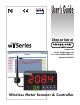
User’s Guide Shop on line at ® omega.com e-mail: info@omega.com For Latest Product Manuals omegamanual.info ® CHART http://192.168.1.200 Save Current Graph P1 Process 50 Min/Max Temperature wiSeries 48.0/41.
It is the policy of OMEGA to comply with all worldwide safety and EMC/EMI regulations that apply. OMEGA is constantly pursuing certification of its products to the European New Approach Directives. OMEGA will add the CE mark to every appropriate device upon certification. The information contained in this document is believed to be correct, but OMEGA Engineering, Inc. accepts no liability for any errors it contains, and reserves the right to alter specifications without notice.
TABLE OF CONTENTS Part 1 Introduction . . . . . . . . . . . . . . . . . . . . . . . . . . . . . . . . . . . . . . . . . . . . . . .1 1.1 Safety Considerations . . . . . . . . . . . . . . . . . . . . . . . . . . . . . .1 1.2 Before You Begin . . . . . . . . . . . . . . . . . . . . . . . . . . . . . . . . . .2 1.3 Description . . . . . . . . . . . . . . . . . . . . . . . . . . . . . . . . . . . . . . .3 Part 2 Hardware . . . . . . . . . . . . . . . . . . . . . . . . . . . . . . . . . . . . . . . . . . . . .
.3.7 Setup . . . . . . . . . . . . . . . . . . . . . . . . . . . . . . . . . . . . . . . . . .39 4.3.7.1 Input . . . . . . . . . . . . . . . . . . . . . . . . . . . . . . . . . . . . . . . . . .39 4.3.7.2 Setpoints & On/Off Control . . . . . . . . . . . . . . . . . . . . . . . . . .40 4.3.7.3 Loop Break . . . . . . . . . . . . . . . . . . . . . . . . . . . . . . . . . . . . . .43 4.3.7.4 Alarms 1 & 2 . . . . . . . . . . . . . . . . . . . . . . . . . . . . . . . . . . . .44 4.3.7.
Figure 2.3 Figure 2.4 Figure 2.5 Figure 2.6 Figure 2.7 Figure 2.8a Figure 2.8b Figure 2.9 Figure 2.10 Figure 2.11 Figure 2.12 Figure 2.13 Figure 3.1 Figure 3.2 Figure 3.3 Figure 3.4 Figure 4.1 Figure 4.2 Figure 4.3 Figure 4.4 Figure 4.5 Figure 4.6 Figure 4.7 Figure 4.8 Figure 4.9 Figure 4.10 Figure 4.11 Figure 4.12 Figure 4.13a Figure 4.13b Figure 4.14 Figure 4.15a Figure 4.15b Figure 4.16 Figure 4.17 Figure 4.18 Figure 4.19a Figure 4.19b Figure 4.20 Figure 4.21 Figure 4.22 Figure 4.23 Figure 4.24 Figure 4.
Figure 4.26 Figure 4.27 Figure 4.28 Figure 4.29 Figure 4.30 Figure 4.31 Figure 5.1 Figure 5.2 Figure 5.3 HTTPget Example of polling End Device . . . . . . . . . . . . . . . . .62 ARP Commands and Responses . . . . . . . . . . . . . . . . . . . . . . .63 iLog Software Logging Data for End Device . . . . . . . . . . . . . . .64 Mail Notifier Main Window . . . . . . . . . . . . . . . . . . . . . . . . . . . .65 Mail Notifier Profile Setup . . . . . . . . . . . . . . . . . . . . . . . . . . . . .
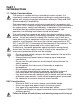
PART 1 INTRODUCTION 1.1 Safety Considerations This device is marked with the international caution symbol. It is important to read this manual before installing or commissioning this device as it contains important information relating to Safety and EMC (Electromagnetic Compatibility). This instrument is a panel mount device protected in accordance with EN 61010-1:2001, electrical safety requirements for electrical equipment for measurement, control and laboratory.
1.2 Before You Begin Inspecting Your Shipment: Remove the packing slip and verify that you have received everything listed. Inspect the container and equipment for signs of damage as soon as you receive the shipment. Note any evidence of rough handling in transit. Immediately report any damage to the shipping agent. The carrier will not honor damage claims unless all shipping material is saved for inspection.
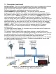
1.3 Description The wi®Series wireless monitoring and control system features meters compatible with a large and growing number of wireless sensors: UWTC “Universal Wireless Thermocouple” Type J, K, T, E, R, S, B, N, and C and UWRTD “Universal Wireless RTD”. For more information about the UWTC and UWRTD, refer to the separate manual for these products. The wiSeries 1/8 DIN Panel Meter & Controller can monitor up to eight (8) wireless sensors.
1.3 Description (continued) DATALOGGING: The OPC Server software makes it easy to integrate the wiSeries wireless sensor system with many popular Data Acquisition and Automation programs offered by NEWPORT, OMEGA, Wonderware, iConics, Intellution, Rockwell Automation, and National Instruments, among others. PROGRAMMABLE COLOR DISPLAY: The wiSeries features patented programmable color displays. The display can be programmed to change color at any Setpoint or Alarm point.
PART 2 HARDWARE 2.1 Physical Characteristics and Mounting 2.1.1 Front Panel Upper Display: Temperature Values Lower Display: Wireless Transmitter ID# 01 thru 08 1 2 %RH D 1 2 C F 1 2 C F Figure 2.1 Front Panel Display 1 2 °C °F Table 2.1 Front Panel Enunciators Output 1 / Setpoint 1 / Alarm 1 indicator Output 2 / Setpoint 2 / Alarm 2 indicator °C unit indicator for Temperature °F unit indicator for Temperature Changes display to Configuration Mode and advances through menu items.
2.1.2 Rear Panel The rear panel connections are shown in Figure 2.2.
2.1.3 Dimensions 3.780 [96.00] 1.890 [48.00] 1 2 %RH D 1 2 C F 1 2 C F 0.700 [17.78] 4.325 [109.85] PANEL THICKNESS 0.25 (6.4) MAX 0.03 (0.6) MIN PANEL CUTOUT 1/8 DIN Figure 2.
2.1.4 Assembly and Mounting 2.1.4.1 Panel Mounting Instruction 1. Using the dimensions from the panel cutout in Figure 2.3, cut an opening in the panel. 2. Remove sleeve from the rear of the case by removing thumbnuts. 3. Insert the case into the opening from the front of the panel, so the gasket seals between the bezel and the front of the panel. 4. Slip the sleeve over the rear of the case. 5. Tighten the thumbnuts to hold the unit firmly in the panel.
2.1.4.2 Antenna Mounting Instruction For best reception: connect the antenna directly to the rear of the meter, if the meter is not installed in a metal panel or enclosure. If the rear of the meter is behind a metal panel or in a cabinet, use a coaxial cable to position the antenna outside outside of the enclosure in the open air. Use the shortest cable that can reach a suitable location. The antenna on this Meter and any End Devices should be installed in a vertical position, pointing towards the sky.
2.1.4.3 Disassembly Instruction If necessary, the board assembly may be removed from the front of the case housing. Warning: Disconnect ac power from the unit before proceeding. 1. Remove the board assembly from the case by pulling at the sides of the bezel. 2. The bezel, along with the board assembly will unlatch from the case housing. • Depending on the size of your Ethernet connector, you may need to disconnect it from the RJ45 jack on the rear of the meter.
2.1.5 Electrical Installation 2.1.5.1 Power Connections Warning: Do not connect ac power to your meter until you have completed all output connections. This meter must only be installed by a specially trained electrician with corresponding qualifications. Failure to follow all instructions and warnings may result in injury! Connect the main power connections as shown below. Use copper conductors only for power connections Figure 2.7 Main Power Connections Table 2.
2.1.5.2 Wiring Outputs This meter has two factory installed outputs. The SPDT Mechanical Relay, SPST Solid State Relay, Pulse and Analog Output Connection are shown below. Use copper conductors only for power connections Figure 2.
2.1.5.
2.1.5.3 Jumper Settings for Display Color Setup To change the color of the lower display follow the instructions below: 1. The unit should be removed from the panel and opened. Refer to Section 2.1.4.3 for assembly and disassembly instructions. 2. Locate S1 jumper, on the back side of the display board. Select the position for your color choice of Red, Green or Amber. Display Board RED S1 GREEN GREEN S1 AMBER S1 (Open) S1 RED 1 8 ON ON 4 32 1 Figure 2.
2.1.5.4 Dip Switches To change the DIP switches, follow the instructions below: 1. The unit should be removed from the panel and opened. Refer to Section 2.1.4.3 for assembly and disassembly instructions. 2. Locate the 4 and 8 position DIP switches, on the top board. The Meter is shipped with all DIP switches in "OFF" position To set the Wireless and Ethernet settings to Factory Default, Refer to Section 7.
2.2 Network Communication Interfaces 2.2.1 10Base-T RJ-45 Pinout The 10BASE-T Ethernet network (RJ-45) system is used in the Meter for network connectivity. The 10 Mbps twisted-pair Ethernet system operates over two pairs of wires. One pair is used for receiving data signals and the other pair is used for transmitting data signals. This means that four pins of the eight-pin connector are used. Pin 1 2 3 4 5 6 7 8 Name +Tx -Tx +RX N/C N/C -Rx N/C N/C Figure 2.
PART 3 NETWORK CONFIGURATION 3.1 Ethernet (MAC) Address MAC (Media Access Control) address is your computer's unique hardware number. When you're connected to the LAN from your computer, a correspondence table relates your IP address to your computer's physical (MAC) address. The MAC address can be found on the label of your meter (see Figure 2.4 and 3.
3.3 DHCP (continued) The Meter is shipped with DHCP disabled (factory default). If fixed or static IP address is desired, the DHCP must be disabled. The DHCP can be enabled by setting the DIP switch # 3 to the “ON” position Figure 3.2 4 Position DIP Switch Setting the Meter’s IP address to 0.0.0.0 will also enable DHCP. 3.4 DNS DNS, Domain Name System enables individual computers and devices to be recognized over a network based on a specific name instead of an IP address.
3.5 IP Address Every active device connected to the TCP/IP network must have a unique IP address. This IP address is used to establish a connection to the Meter. Every computer using TCP/IP should have a unique 32-bit address which is divided into two portions, the network ID and the host ID. For instance, every computer on the same network uses the same network ID. At the same time, all of them have a different host ID. For more details about the IP address see Appendix B. 3.5.
3.5.2 Changing TCP/IP Properties on Your Computer Go to your computer’s Control Panel then Network Connections. Pick the network with the proper Ethernet card. Right click and choose Properties Look for Internet Protocol, click on it and press Properties Figure 3.3 Network Connections Setup the IP address (in this case, 192.168.1.1) as shown below and press OK You can access the Meter’s web server via any internet browser using IP address of 192.168.1.200.
PART 4 NETWORK OPERATIONS This Meter can be used and configured in several ways, depending on user’s preference and network setup. It can be configured using a Web browser, like Internet Explorer. It can also be configured using the iConnect Configuration Software. If DHCP and DNS servers are configured to exchange information, the connection will be very simple. All you need to do is to enable DHCP on the Meter (see Section 3.
4.1 iConnect Software The Meter may also be assigned an IP Address by using the iConnect software. a) Download the iConnect software from the website listed in this manual. b) Install iConnect software on a networked PC. This software is compatible with Windows 95, 98, NT, 2000, and XP. c) Use iConnect to assign an IP address to the Meter and access its web pages for configuration. You can also use any standard web browser to access the Wireless System’ web pages.
4.1 iConnect Software (continued) d) To access the Wireless System for Configuration: Click on the “View Webpage” button, you will access the Wireless System’s home page, refer to Section 4.3 for details. Figure 4.
4.2 Setting a New IP Address over the Network Besides using the iConnect software, you may use the Meter’s default IP address to access it and assign a new IP address to it. The Meter is shipped with a default IP address of 192.168.1.200 and Subnet Mask of 255.255.255.0. You can configure your PC’s Network connection with an IP address that is in the same range as the Meter’s IP address (192.168.1.x) and connect to the Meter using a crossover network cable between your PC and the Meter.
4.3 Meter’s Configurations and Operations Using a web browser, you should be able to view the Meter’s homepage. • Start your web browser. • From the browser you type http://wisxxxx using the last four-digits from the MAC address label located on the Meter (see Figure 3.1), if DHCP and DNS are used. If a static IP address is used, then simply type http://x.x.x.x, where x.x.x.x is the Meter’s IP address. • The Home Page, will be displayed. Figure 4.
4.3 Meter’s Configurations and Operations (continued) LOGIN http://192.168.1.200 ADMINISTRATOR http://192.168.1.200 LOGIN ADMINISTRATOR Figure 4.6 LOGIN and ADMINISTRATOR Passwords There are 2 different access levels: 1. ADMINISTRATOR Password (administrator) allows certain groups and individual users to access and modify parameters without any restrictions. The default password is 00000000. This password can be up to 16 alphanumeric case-sensitive characters. 2.
4.3.2 Get Readings from the End Device Once you see the End Device’s LED blinking periodically, it means it is sending data which will appear on the “Readings” page. To view the data in a chart format, you can use the “Chart” page. Click on Readings from the Home Page, the following page will appear, showing updates of the Process and Ambient Temperature. Lab 100 Process 73 wiSeries F Ambient 70 F ID: 1 Sequence: 10 Strength: 100% Success: 100% Battery: 3.
4.3.2 Get Readings from the End Device (continued) The “Readings” fields are defined as follows: Name: End Device’s name Reading Values: The order from left to right is Process Temperature, then Ambient. First Reading: Process - external thermocouple or RTD temperature reading with temperature unit. Second Reading: Ambient - built-in sensor temperature reading with temperature unit. Reading “Open” indicates that no sensing device is detected. ID: End Device ID/address Sequence: Sequence number [0-255 ].
4.3.3 Java Runtime Environment Setup If your computer does not have Java installed, please download from java.sun.com. You can change the Java setting by clicking its icon in Control Panel. To load the applet, you have to enable the web browser and disable cache. 4.3.3.1 Java Runtime Environment 1.5 (5.0) Setup Instructions 1. Go to your computer's Control Panel. Open the Java Plug-in 2. Click on "Settings" & "View Applets" in the "General" tab. 3.
For Java 1.6.x.x it is similar to Java 1.5.x.x but there is no need to remove CACHE. 4.3.3.2 Java Runtime Environment 1.4 Setup Instructions 1. Go to your computer's Control Panel. Open the Java Plug-in 2. Select the "Cache" Tab Un-check the "Enable Caching" box 3. Select the "Proxy" Tab. Follow these Browser Proxy Selection instructions below. (Generally, un-check the box if accessing the Meter on your local network and check the box for access from your internal network to the internet.) 4.
4.3.3.3 Browser Proxy Selection Accessing Meter units within your internal network • Usually when the computer and Meters are on an internal network, you will not use Proxy server access. • You should un-check the "Use Browser Settings" option on the "Proxy" tab. Accessing Meter units using the internet • Often the web browser will use Proxy server access to the internet. In such cases, the default Java runtime settings on the "Proxy" tab should suffice.
4.3.4 Java Policy To activate data logging and save graphs from the Java applets, it is necessary to create a Java Policy file and copy it onto a folder. 1) Open a Notepad file and using the IP address of the Meter type the following: grant codeBase “http://192.168.1.200/*” { Permission java.security.AllPermission “*”, “*”; }; This file should have the IP address of the Meter; in this case the default IP address is 192.168.1.200.
4.3.4 Java Policy (continued) 5)Change Java Applet’s Runtime Parameters found on the following path: a. Control Panel --> Java --> Java Control Panel --> Java Tab --> View b. Inside the box under the Java Runtime Parameters type the following: “-Djava.security.policy=C:\0_JAVAPOLICY\java_policy.txt” c. Click OK on the Java Runtime Settings window. d. Click Apply on the Java Control Panel window and then OK. 6) Close all opened Web browser.
4.3.5 Chart Click on Chart from the Home Page, the following page will appear. The Java™ Applet graph displays Process Temperature and Ambient Temperature. It can be charted across the full span or within any narrow range (such as 20 to 30ºC). If a blank screen appears without any “java application running” or image of a “Java logo”, please verify you have the latest Java Runtime Environment installed and configured according to the instructions (refer to Section 4.3.3.1).
4.3.5 Chart (continued) Save Current Graph: Save the current graph in PNG (Portable Network Graphics) format. The filename has the extension .png. Max/Min Temperature: Maximum and minimum temperature of the current graph. If a sensor is selected (trend line and sensor name turns bold), its most current temperature reading is shown here. Reading “Open” indicates that no sensing device is detected. Temperature Unit: Temperature unit to be used, either ºC or ºF.
4.3.6 Controller Setup The Meter has two modes of operations. One is through the Front Panel Buttons (please refer to Front Panel Supplement for more details), and the other is by using the browser to configure the settings. Click on Controller from the Home Page. In a few seconds the following page will appear. CONTROLLER SETUP Address http://192.168.1.
4.3.6 Controller Setup (continued) This version of the menu will appear only if you have the Analog Output Option installed in your Meter. CONTROLLER SETUP Address http://192.168.1.
4.3.6 Controller Setup (continued) Below are the definitions of terms used in the Controller Setup page. A) Setup: Clicking on the options shown, allows user to modify the different parameters shown under this menu (see Section 4.3.7. Setup Page for more details) B) Monitor: Scrolling: If checked, the Meter will display data from all the End Devices. Otherwise, it only displays data from the End Device specified on Device ID. End Device ID: Address/ID of the End Device that will be display on the Meter.
4.3.7 Setup This section is used to configure the Meter online. Click on the specific settings to change the parameters on that section 4.3.7.1 Input Control End Device ID: Insert the End Device ID number that will be used as input to control Filter: This option allows the user to specify the number of readings stored in the Digital Averaging Filter. Temperature Unit: Unit of temperature readings, [ ºC or ºF ]. SETUP Address http://192.168.1.
4.3.7.2 Setpoints & On/Off Control Auto Setpoint Deviation: If “enabled”, allows changes to Setpoint 1 to be made automatically to Setpoint 2. This mode is very helpful if the Temperature changes often. In Setpoint Deviation Mode, set SP2 a certain number of degrees or counts away from SP1--this relation remains fixed when SP1 is changed. For instance: Setting SP1=200 and SP2=20 and enabling SP Deviation means that the absolute value of SP2=220. Moving SP1 to 300, the absolute value of SP2 becomes 320.
4.3.7.2 Setpoints & On/Off Control (continued) SETUP Address http://192.168.1.200 SETUP Setpoints & On/Off Control Auto Setpoint Deviation Disabled Setpoint 1 Setpoint 2 0 100 Permanent Store On/Off 1 DeadBand Action On/Off 2 DeadBand Action Disabled 0 Reverse Disabled 0 Direct Update Cancel Main Menu Figure 4.
4.3.7.2 Setpoints & On/Off Control (continued) This version of the menu will appear only if you have the Analog Output Option installed in your Meter. SETUP Address http://192.168.1.200 SETUP Setpoints & On/Off Control Setpoint 2 100 Permanent Store On/Off 2 DeadBand Action Disabled 10 Direct Update Cancel Main Menu Figure 4.
4.3.7.3 Loop Break Loop Break: can be enabled or disabled. Loop Break is an additional safety feature intended to monitor the rate of change of the temperature value, while approaching the Setpoints. It is strictly intended as an additional warning system; therefore its use is entirely optional. An active Loop Break will cause the temperature digits to blink in a rotating pattern.
4.3.7.4 Alarms 1 & 2 Alarm 1 (or 2) Relay: To enable or disable (no alarm functions) the alarms . Alarm 1 (or 2) Low: editable box for the low alarm value. Alarm 1 (or 2) High: editable box for the high alarm value. Active: If Above, Alarm condition triggered when the process variable is greater than the Alarm Hi Value (Low value ignored). If Below, Alarm condition triggered when the process variable is less than the Alarm Low Value (Hi value ignored).
4.3.7.4 Alarms 1 & 2 (continued) SETUP Address http://192.168.1.200 SETUP Alarm 1 Alarm 1 Relay Alarm 1 Low Enabled Alarm 1 High Active Normally Latch Absolute Alarm at Power On: Alarm could be 100 0 triggered immediately by non-controlling end device at startup. Above Open Unlatched Absolute Enabled Update Cancel Main Menu Figure 4.
4.3.7.5 Analog Output Retransmission This menu will appear only if you have the Analog Output Option installed in your Meter. SETUP Address http://192.168.1.200 SETUP Analog Output Retransmission Retransmission Voltage/Current Enabled Voltage Input Low Output Low Input High Output High 0 0.00 Min. 0V 100 10.00 Max. 10V Update Cancel Main Menu Figure 4.
4.3.7.6 Display This submenu allows the user to select the color of the display--green, red, amber. Screen Update: Editable box to enter the display time in seconds between each End Device. Normal: Choose the display color of temperature when it is in the normal stage. Alarm 1: Choose the display color of temperature when alarm 1 is true. Alarm 2: Choose the display color of temperature when alarm 2 is true. In order to display one color, set the same display color on all three submenus.
4.3.7.6 Display (continued) This version of the menu will appear only if you have the Analog Output Option installed in your Meter. This submenu allows the user to select the color of the display--green, red, amber. Screen Update: Editable box to enter the display time in seconds between each End Device. Normal: Choose the display color of temperature when it is in the normal stage. Alarm 2: Choose the display color of temperature when alarm 2 is true.
4.3.7.6.1 Display Color Examples Press Press Press 1) Display flashes previous selection for “Alarm 2 Color Display”. 2) Scroll through the available selections: G R N , R E d or A M BR . 3) Display shows S tR d stored message momentarily and then momentarily shows the software version number, followed by R S t Reset, and then proceeds to the Run Mode. Example 1: Output 1 & Output 2 = SSR Alarm Setup: Absolute, Above, Alarm 2 HI Value “ALR.H” = 200, Alarm 1 HI Value “ALR.
4.3.7.6.1 Display Color Examples (continued) Example 3: Output 1 = Analog Output (Alarm 1 disabled), Setpoint 1 = 300, Output 2 = Relay, Setpoint 2 = 200 Alarm 1 & 2 Setup: Deviation, Band, “ALR.H” = 10 Color Display Setup: “N.CLR” = Green, “1.CLR” = Amber, “2.
4.3.7.7 Passcode ID To prevent unauthorized tampering with the setup parameters, the Meter provides protection by requiring the user to enter the ID Code before allowing access to subsequent menus of the Meter’s front panel. If the ID Code entered does not match the ID Code stored, the Meter responds with an error message and access to subsequent menus will be denied.
4.3.8 Network Setup Click on Network Setup from the Home Page, the following page will appear. NETWORK SETUP Address http://192.168.1.200 NETWORK SETUP A General Secured Applet Title wiSeries Terminal Server TCP/UDP TCP B Server Type Command Forward CR Disable Number of Connections 1 Port 02000 C Remote Access (Tunneling) Remote IP Address 0.0.0.0 Remote Port 02000 Remote Access Disable Update Main Menu Figure 4.
4.3.8 Network Setup (continued) A) General Secured Applet: If checked, the LOGIN password is required to open “Readings” and “Chart” pages. Title: Meter’s name [maximum of 16 alphanumeric characters] B) Terminal Server TCP/UDP*: The Meter supports TCP and UDP protocols (default is TCP). If UDP is selected, it can be configured either for Broadcast UDP or Directed UDP. In case of Broadcast UDP, the Meter will transmit the data to every node on the network.
4.3.9 End Device Setup Click on End Device from the Home Page, the following page will appear. END DEVICE SETUP Address http://192.168.1.
4.3.9 End Device Setup (continued) The End Device Setup Page is for configuring the End Device parameters such as Name and Update Rate. Non zero update rate will enable success calculation and lost detection features. Update rate should reflect the actual blinking interval in order to enhance the accuracy of success calculation and lost detection. #: End Device ID/address configured on the End Device. Click on the number (1 to 8) to view device and modify End Device Parameters.
4.3.9.1 End Device Parameters END DEVICE PARAMETERS Address http://192.168.1.200 END DEVICE PARAMETERS End Device 1 Device Name: ABCDEFGH Update: 120 Sec Sensor1 Remote Display Format: 0000000F Remote End Char(Hex): 0x 0D Offset(xxxx): 0 Display: C Alarm Sensor2 Remote Display Format: 0000000F Remote End Char(Hex): 0x 0D Offset(xxxx): 0 C Update Cancel Device Reset Main Menu Figure 4.
4.3.9.1 End Device Parameters (continued) Device Name: Name of this End Device. Update (Seconds): How often this End Device is sending its data to the Receiver. The default shown “update second” is 0 seconds. This update corresponds to the sampling rate configured by using the Configuration Wizard. For detailed steps on how to configure the sampling rate, please refer to Section 4.1 of the UWTC Manual.
4.3.9.1 End Device Parameters (continued) Offset: If it’s determined that the readings are slightly off, the user can manually assign numerical values to adjust the readings for temperature. The unit must be in degree C. Display: To enable or disable numerical display on the Meter’s Front Panel. By default, the box is checked (enabled). Alarm: To enable or disable alarms for that particular sensor. By default, the box is checked (enabled).
4.3.10 Access Control (continued) Login Password: This allows users to access and modify all of the Wireless System Home Page menu items, except “Access Control”, which requires an Administrator password. The default Login password is 12345678. This password can be up to 16 alpha-numeric case-sensitive characters. If there is no Login Password assigned (blank box) the Wireless System will not require a password to access and modify any of the menu items, except the “Access Control” page.
4.4 Telnet Setup In the “Network Setup” page, under the Terminal Server section, set the TCP Connections to 1 - 5 other than 0, and use a telnet emulation program to connect to the Meter (using Port 2000). The command can be sent to query the Meter and get a response back. Table 4.
4.5 HTTPget Program The Httpget software is used to send a single HTTP or TCP request to the Meter. In contrast, the telnet or Hyperterminal programs allow a continuous connection with multiple requests to be sent to the Meter. Generally HTTPget is used for simply programming an IP address to the Meter or for quickly obtaining a reading from a End Device. The Meter must be configured from the “Network Setup” page so that the "TCP Connections" indicates any number between 1 and 5.
4.5.1 HTTPget using Port 2000 (continued) 3). Next run HTTPget with the options displayed below httpget -r -S *SR00z 192.168.1.135:2000 -C1 -q where: -r –S are parameters needed for the the command string Command (See Table 4.1) 192.168.1.135 is an IP address 2000 is a socket port number -C1 closes the TCP connection after 1 second -q displays no error messages once the connection is closed Figure 4.26 HTTPget Example of Polling End Device #2,6,7 4.5.
4.6 ARP Protocol ARP is the Internet layer protocol responsible for matching or obtaining the MAC (hardware) address that corresponds to a particular IP address. The ARP command allows the user to view the current contents of the ARP cache of the local computer (residing on the same network). Microsoft includes the ARP.EXE utility for viewing and modifying the ARP cache with its Windows products.
4.7 iLog Software This is an Excel application software that can log temperature from the Meter over the local network (Ethernet) or the internet. a) Download the iLog software from the website listed in this manual. b) Install iLog software on a networked PC. This software is compatible with Windows 95, 98, NT, 2000, and XP. c) For complete information of how to use the iLog software, click on the HELP button. d) There is a list of Error Messages in Appendix E. Figure 4.
4.8 Mail Notifier Software For complete information of how to use the Mail Notifier software, click on the Help menu of the main window. The Mail Notifier software generates email notifications for alarm conditions. Users can be notified automatically of alarm conditions monitored via internet connections throughout the world. By use of the email forwarding of alarm conditions, alarm conditions can be monitored on a network isolated from the internet and forwarded to connections on the Internet.
4.8.2 Program Options Setup and Configuration Complete program setup requires: • Entering a recipient for the email • Specifying connection details to MAPI services. • Defining alarms for devices, and selecting how and when the email will be active. Options Send To Email Setup Content Startup General Mail Server MAPI Use Login Box Name/Profile Password Email Address Help MS Outlook Outlook 2002 OK Cancel Figure 4.
4.8.3 Device Setting and Configuration The Meter and End Devices should first be configured and ready to use. Make sure to have the following settings in the ”Network” web page of the Meter (Figure 4.21) .
4.8.3 Device Setting and Configuration (continued) Alarm Editor Device Info (1 of 2) Server IP Address 192.168.1.200 Socket Number 2000 Bus Address/Device ID 3 OK Cancel Help Description Src ID Add Dev1 SR##a zRdgA Reading Cmd Del Only Monitor Access to iServer device Alarm Configuration Alarm Type Alarm High Info Message Alarm High 73 Email Interval Alarm Low 0 Monitor Interval 0.5 min. Alarm Hold Time 0.0 min. 0.05 Figure 4.31 Mail Notifier Device Setting 68 hrs.
Part 5 ENVIRONMENT / OPERATING CONDITIONS The End Device and Meter are designed to be fixed mounted and operated in a clean and dry environment. Care should be taken to prevent the components of your wireless system from being exposed to moisture, toxic chemicals, extreme cold or hot temperature that are outside the specification listed in this manual. The following is a list of basic good practice you should apply when operating this Wireless System. 1.
7. Where possible, try to ensure an uninterrupted line-of-sight between nodes. Avoid obscuring objects (e.g. metal pillars, posts, sign) near the antenna. A close object obscures a wider range of solid angle. 8. It is important to understand that the environment may change over time due to new equipment or machinery being installed, building construction, etc. If new obstacles exist between the End Device and Meter, antenna angle may need to be re-adjusted and/or the unit has to be relocated. 9.
5.2 With Line-of-Sight When installing the Meter it is important to position your device in such a way to optimize the antenna location within what’s known as the “Fresnel Zone”. The Fresnel Zone can be thought of as a football-shaped invisible tunnel between two locations that provides a path for RF signals between the End Device and the Meter. Figure 5.2 Fresnel Zone In order to achieve maximum range, the football-shaped path in which radio waves travel must be free of obstructions.
5.3 Without Line-of-Sight When line-of-sight is not possible, signal penetrates and is reflected by different objects to reach the destination. Therefore, it is important to learn about how these materials would affect signal propagation. Depending on the thickness, moisture content and angle of incidence, a wall may allow between 1% and 25% of the radio power to pass through. Metal panel or metalized glass window will not allow much radio power to pass through.
PART 6 SPECIFICATIONS METER SPECIFICATIONS NMRR: 60 dB CMRR: 120 dB Digital Filter: Programmable Display: 4-digit, 9-segment LED, 10.2mm (0.40”) and 21mm (0.83”) red, green and amber programmable colors CONTROL OUTPUT 1 & 2 Relay: 250 Vac or 30 Vdc @ 3 A (Resistive Load); configurable for on/off Output 1: SPDT type, can be configured as Alarm 1 output Output 2: SPDT type, can be configured as Alarm 2 output SSR: 20-265 Vac @ 0.05-0.
INSULATION Power to Output 2300 Vac per 1 min. test 1500 Vac per 1 min. test (Low Voltage/Power Option) Power to Relays/SSR Outputs 2300 Vac per 1 min. test Relays/SSR to Relay/SSR Outputs 2300 Vac per 1 min. test GENERAL Line Voltage/Power: 90-240 Vac +/-10%, 50-400 Hz*; 110-375 Vdc, equivalent voltage; 5 W * No CE compliance above 60 Hz Low Voltage/Power Option: 12-36 Vdc or 24 Vac** +/-10%, 3 W External power source must meet Safety Agency Approvals.
INTERFACE SPECIFICATIONS Ethernet: Standards Compliance IEEE 802.3 10Base-T (RJ45) Supported Protocols: TCP/IP, ARP, ICMP, DHCP, DNS, HTTP, and Telnet LED Indicators: Network Activity, Network Link, Diagnostics, Receive & Power Management: Device configuration and monitoring through embedded WEB server Embedded WEB Server: Serves WEB pages (Java™ Applets) containing realtime data and live updated charts within definable time intervals. WIRELESS COMMUNICATION Standard: IEEE 802.15.4 Frequency: 2.
PART 7 FACTORY PRESET VALUES To set the Wireless and Ethernet settings back to Factory Default do the following to the DIP switches (see Figure 2.11). To set the Ethernet board to Factory Default settings: 1) Put the 4 position DIP switch #2 to ON position (it does not matter if the Meter is On or Off). 2) Power-cycle the Meter and wait about 10 seconds until the Meter fully boots up.
Table 7.
Table 7.1 Factory Preset Values (continued) Analog Output Retransmission Retransmission Enabled Voltage/Current Voltage Input Low 0 Output Low 0.00 Input High 100 Output High 10.00 Monitor Scrolling End Device ID Permanent Store Transmit Power Channel 12 Transmit Power Range 20dBm Misc PID 13106 (version x.x) iSeries Firmware Ver x.
Table 7.
APPENDIX A GLOSSARY User of this manual should be familiar with following definitions: ARP (Address Resolution Protocol) is a protocol for mapping an Internet Protocol address (IP address) to a physical machine address that is recognized in the local network. For example, the IP address in use today is an address that is 32-bits long. In an Ethernet local area network, however, addresses for attached devices are 48-bits long.
Appendix B IP Address An IP address is a unique 32-bit address assigned to a computer and includes: • A network ID number identifying a network. • A host ID number identifying a computer on the network. All IP addresses have been divided into three smaller groups (classes) A, B and C • Class A addresses have 8-bits of network ID and 24-bits of host ID. They can support a large number of hosts, approximately 2 = 16,777,216 computers per network. The IP addresses range in binary from 00000001.xxxxxxxx.
Appendix C IP Netmask IP Netmask or Subnet Mask is a 32-bit pattern of ones and zeros used to determine network portion of an IP address from the host portion of the IP address. Subnet mask is a network ID that is created by borrowing bits from host portion of IP address and using them as part of a network ID. The table below shows a default subnet mask for address Classes A, B, and C.
Appendix D ASCII Char NUL SOH STX ETX EOT ENQ ACK BEL BS HT LF VT FF CR SO SI DLE DC1 DC2 DC3 DC4 NAK SYN ETB CAN EM SUB ESC FS GS RS US SP ! " # $ % & ‘ ( ) * + , .
Appendix / 0 1 2 3 4 5 6 7 8 9 : ; < = > ? D 47 48 49 50 51 52 53 54 55 56 57 58 59 60 61 62 63 2F 30 31 32 33 34 35 36 37 38 39 3A 3B 3C 3D 3E 3F ASCII Chart Continuation 00101111 o 111 p 00110000 112 q 00110001 113 00110010 r 114 00110011 s 115 00110100 t 116 00110101 u 117 00110110 v 118 00110111 w 119 00111000 x 120 y 00111001 121 00111010 z 122 { 00111011 123 | 00111100 124 } 00111101 125 00111110 ~ 126 00111111 DEL 127 6F 70 71 72 73 74 75 76 77 78 79 7A 7B 7C 7D 7E 7F 01101111 01110000 01110001
Appendix E iLog Error Messages Error # Description Note -10005 Failed to find the Meter. Ethernet cable is disconnected, iServer is powered off, connections across the firewall require longer “connection to socket time out” setting. -8003 User stopped logging readings. -10006 Windows socket was closed. -10007 Windows socket error. Wrong IP or wrong Port number was used. -10011 No data was sent. -10008 The Meter failed to respond to a request. Response came empty.
NOTES
NOTES
NOTES
WARRANTY/DISCLAIMER OMEGA ENGINEERING, INC. warrants this unit to be free of defects in materials and workmanship for a period of one (1) year from the date of purchase. In addition to OMEGA’s standard warranty period, OMEGA Engineering will extend the warranty period for one (1) additional year if the warranty card enclosed with each instrument is returned to OMEGA. If the unit malfunctions, it must be returned to the factory for evaluation.
Where Do I Find Everything I Need for Process Measurement and Control? OMEGA…Of Course! Shop on line at omega.