CN3271-add2.pmd 1 19/08/2004, 16.
Internet e-mail info@omega.com OMEGAnet OMEGAnet® On-Line Service www.omega.com For immediate technical or application assistance: Service North America USA: ISO 9001 Certified One Omega Drive, Box 4047 Stamford CT 06907-0047 Tel: (203) 359-1660 FAX: (203) 359-7700 e-mail: info@omega.
APPROVALS This instrument is U.L. and c.U.L. approved as controller. CONTENTS MOUNTING REQUIREMENTS ............................ 1 DIMENSIONS AND REAR TERMINALS ................ 2 PANEL CUT OUT ........................................... 3 WIRING GUIDELINES ...................................... 3 PRELIMINARY HARDWARE SETTINGS ............... 8 CONFIGURATION PROCEDURE ........................ 9 OPERATING MODE ...................................... 15 Normal display mode ..............................
MOUNTING REQUIREMENTS The instrument is shipped with a rubber panel gasket (50 to 60 Sh). To insure the IP65 and NEMA 4 protection, insert the panel gasket between the instrument and the panel as shown below. Select a mounting location with the following characteristics: 1) Minimal vibration. 2) An ambient temperature range between 0 and 50°C (32 and 122 °F). 3) Easy access to the rear of the instrument. 4) No corrosive gases (sulfuric gas, ammonia, etc.). 5) No water or other fluid (i.e. condensation).
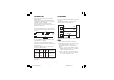
DIMENSIONS AND REAR TERMINAL BLOCKS Chromalox Without RS-485 With RS-485 Fig.2 2 LHL-1-NEUTRO.pmd 2 19/04/2004, 15.
PANEL CUTOUT WIRING GUIDELINES A) Measuring Inputs NOTE: Any external components (like Zener diodes, etc.) connected between sensor and input terminals may cause errors in measurement due to excessive and/or not balanced line resistance or possible leakage currents. TC Input + 10 _ 9 Shield + 10 Fig.3 _ 9 Shield Fig. 4 THERMOCOUPLE INPUT WIRING NOTE: 1) Do not run input wires with power cables. 2) For TC wiring use proper compensating cable, preferably shielded (see Appendix B).
LINEAR INPUT RTD INPUT RTD RTD 10 + _ 9 mA, mV or V Shield 8 9 10 8 9 + 10 10 _ 9 Fig. 5 RTD INPUT WIRING G NOTE NOTE: 1) Don’t run input wires together with power cables. 2) Pay attention to the line resistance; a high line resistance may cause measurement errors. 3) When shielded cable is used, it should be grounded at one side only to avoid ground loop currents. 4) The resistance of the 3 wires must be the same. Fig.
B) Logic Input (for models with RS-485 only) C.1) Relay Outputs This input is used for remote acknowledgement (reset). Safety note: - Do not run logic input wiring with AC power cables. - Use an external dry contact capable of switching 0.5 mA, 5 Vdc. - The instrument needs 100 ms to recognize a contact status variation. - The logic inputs are NOT isolated from the measuring input. OUT 1 1 Class 1 2 3 OUT 2 Class 1 (Alarm) 6 7 Logic input 14 NO - OUT 1 C - OUT 1 NC - OUT 1 C NO Fig.
C.2) Inductive Loads High voltage transients may occur switching inductive loads. Through the internal contacts these transients may introduce disturbances which can affect the performance of the instrument. For all the outputs, the internal protection (varistor) assures a correct protection up to 0.5 A of inductive component. D) Serial Interface For units built with optional RS-485 communication interface. RS-485 interface allows to connect up to 30 devices with one remote master unit.
I N S T R U M E N T I N S T R U M E N T E) Power Line and grounding 11 12 13 A'/A A/A' B'/B B/B' COMMON 4 M A S T E R 5 N, L2 POWER SUPPLY 100 to 240 Vac 24 Vac/Vdc N, L2 R (S,T), L1 Fig.12 R (S,T), L1 NOTES: 1) Before connecting the power line, check that the voltage is correct (see Model Number). 2) For supply connections use 16 AWG or larger wires rated for at least 75 °C. 3) Use copper conductors only. 4) Do not run input wires with power cables. 5) Polarity does not matter for 24 Vdc wiring.
PRELIMINARY HARDWARE SETTINGS High - Low Limiter without RS-485 V101 1) Remove the instrument from its case. 2) Set J106 according to the desired input type as shown in the following figure. INPUT TYPE 2 4 6 8 1 3 5 7 J106 J106 1-2 3-4 5-6 7-8 TC-RTD close open open open 60 mV close open open open 5V open close open open 10 V open open close open 20 mA open open open close Fig.13.B High - Low Limiter with RS-485 2 4 6 8 1 3 5 7 J106 Fig.13.
CONFIGURATION PROCEDURE The following is a complete list of parameters. The lower display will show the parameter code (L1 to d1) and the upper display will show the selection code or numerical value. No timeout is applied in the configuration mode. CONFIGURATION KEY FUNCTIONS RESET In Configuration Mode, it is used only to scroll back parameters without to memorize a new parameter value. Used in Configuration Mode to decrease the parameter value.
r 1 =Input Type 0 = TC J 1 = TC K 2 = TC T 3 = TC E 4 = TC N 5 = TC S 6 = TC R 7 = TC B 8 = TC L 9 = TC U 10 = TC G 11 = TC D 12 = TC C 13 = TC Plat. II 14 = RTD Pt 100 15 = Linear 16 = Linear 17 = Linear 18 = Linear 19 = Linear 20 = Linear 21 = Linear 22 = Linear 23 = TC J 24 = TC K 25 = TC T 26 = TC E 27 = TC N 28 = TC S 29 = TC R 30 = TC B 31 = TC L 32 = TC U 33 = TC G 34 = TC D 35 = TC C 36 = TC Plat.
Hi. = High limit (for heating process) Lo. = Low limit (for cooling process) Hi.Lo = High and low limit (for special process) generated the shutdown, no longer exists and the acknowledge action has been performed. The upper display flashes during a shutdown and returns to a steady display when the shutdown condition no longer exists. When C2 = 0 and OUT 1 is OFF, the RESET LED is ON.
HS C4 0 Su (Limiter threshold) (Limiter Hysteresis) 1 ON Relay OUT 1 OFF C5 = Time Constant of the Filter applied to the Measured Value for Limit Action. Range: From 0 (filter OFF) to 8 seconds Note: First order filter with selected time Constant. ON “Reset” LED OFF Flash Upper display Steady FLASH FLASH = Shutdown memory = The shutdown condition will be saved (at next power up it will be reactivated) = The shutdown condition will be lost in case of power down A, B, C = Acknowledgment actions.
Example for P2 = H.L. NOTE: 1) For band alarm, H.A./H.A.Ac/H.L. signifies outside band alarm, while L.A./ L.A.Ac/L.L. signifies inside band alarm. 2) The "Silence" function allows the manual reset of the alarm even if the alarm condition is still in progress. Alarm status* Relay Non alarm status Example for P2 = H.A.
P4 = Alarm Standby (mask) Function (Skipped if option is not available or P1= none) OFF = Standby function disabled On = Standby function enabled d1 = Digital Input (contact closure) (This is a read only parameter) Enb = Digital input enabled dlS = Digital input disabled (The digital input is used as a remote Acknowledgment .
OPERATING MODE 1) Remove the instrument from its case. 2) Set switch V101 (see fig. 13) to the closed position. 3) Re-insert the instrument in its case. 4) Switch on the instrument. shows "Ph.". If no shutdown condition was detected, the upper display will show “- - - -”. This information is not available if C1 = HI.Lo. The information is lost at power down and at powerup the device will display the process variable. Normal Display Mode On powerup the device starts in the "Normal Display Mode.
Indicators “RESET“ =Indicates control output 1 status as follows: a) When C2 parameter has been configured equal to 0, LED ON when Output 1 is OFF LED OFF when Output 1 is ON b) When C2 parameter has been configured equal to 1, LED flashes when Output 1 is OFF LED ON when Output 1 is OFF and acknowledged LED OFF when Output is ON “ALM” = Indicates alarm status as follows: - Flashes when alarm is ON - ON when alarm has been resetted but the alarm condition is still present.
To switch from LOCKED to UNLOCKED, assign to the “nn” parameter a value equal to the “n1” parameter setting. To switch from UNLOCKED to LOCKED, assign to the “nn” parameter any number other than the n1 parameter setting. When the device is in remote mode (the serial link controls the device) no parameters can be modified. nn Software Key (Skipped if n1 = 0 or 1) ON = the device is LOCKED. OFF = the device is UNLOCKED.
Limiter function The relay of the output 1 operates in fail-safe mode (relay de-energized during shutdown condition) and latching mode. The length of the shutdown condition and max/min measured values are stored in memory and available for viewing (see “Normal Display Mode”) until the next shutdown condition occurs. These informations are lost at power down.
Alarm functions (Skipped if option is not available or P1 = none) The alarm can be programmed as: - process alarm - band alarm - deviation alarm. Band and deviation alarms are referred to the limiter threshold and are possible only if an high limiter or a low limiter function has been selected. For all the alarm types, it is possible to select automatic or manual reset or the “Silence” function.
Error Messages On power up, the instrument performs a selfdiagnostic test. When an error is detected, the lower display shows an "Er" indication while the upper display shows the code of the detected error. ERROR MESSAGES Overrange, Underrange and Sensor Break Indications This device detects input fault conditions. (OVERRANGE, UNDERRANGE OR SENSOR BREAK).
D/A conversion conversion: dual slope integration. Sampling time : - for linear inputs = 250 ms. - for TC or RTD inputs = 500 ms. Display updating time: time 500 ms. Resolution Resolution: 30000 counts. Temperature Drift (CJ excluded) - Less than 200 ppm/°C of full span for mV and TC ranges 0, 1, 3, 4, 8, 13, 23, 24, 26, 27, 31, 36 (CJ excluded).
B) RTD (R Resistance Temperature Detector) Input Input: for RTD Pt 100 Ω, 3 wire connection. Input circuit circuit: current injection. °C/°F selection selection: via front pushbuttons or serial link. Line resistance resistance: automatic compensation up to 20 Ω/wire with no measurable error. Calibration Calibration: according to DIN 43760 Burn out : The instrument detect the open condition of one or more wires. It is able to detect also the short circuit of the sensor.
OUTPUTS STANDARD RANGES TABLE Input type 15 16 17 18 19 20 21 22 0 - 60 mV 12 - 60 mV 0 - 20 mA 4 - 20 mA 0- 5 V 1- 5 V 0 - 10 V 2 - 10 V impedance Accuracy Output updating time : - 250 ms when a linear input is selected - 500 ms when a TC or RTD input is selected. > 1 MΩ <5Ω > 400 kΩ OUTPUT 1 Type: relay SPDT contact . Contact rated rated: 3 A at 250 V AC on resistive load. Function Function: Safety limiter output. Action Action: reverse (fail-safe). 0.
MAINTENANCE 1) REMOVE POWER FROM THE POWER SUPPLY TERMINALS AND FROM RELAY OUTPUT TERMINALS 2) Remove the instrument from case. 3) Using a vacuum cleaner or a compressed air jet (max. 3 kg/cm2) remove all deposit of dust and dirt which may be present on the louvers and on the internal circuits trying to be careful for not damage the electronic components.
APPENDIX A DEFAULT PARAMETERS procedure is complete and the instrument reverts to the “Normal Display Mode.” The following is a list of the default operating parameters loaded during the procedure: DEFAULT PARAMETERS Default Operating Parameters List Parameter Default Value Alarm Acknowledge OFF Software Key Unlock Setpoint Threshold Low range value (if low limit) High range value (if high or high/low limit) Setpoint1 Threshold Low range value Setpoint Threshold Hysteresis 0.
Loading Default Configuration Parameters The configuration parameters can be loaded with predetermined default values. These are the settings loaded into the instrument prior to shipment from the factory. To load the default values proceed as follows: f) Press the FUNC key; the display will show: a ) Internal switch V101 must be open. b) The upper display will show: c) Press the key; the lower display will show the firmware version.
PARA. Table 1 Table 2 European American L1 nbUS nbUS L2 1 1 L3 19200 19200 L4 8E 8E r1 Type J Type J (-100 to 1000 °C) (-150 to 1830 °F) r2 ----. ----. r3 -100 -150 r4 1000 1830 r5 0 0 r6 1 second 1 second r7 uP uP c1 Hi Hi c2 1 0 c3 Auto Auto c4 0 0 c5 1 second 1 second P1 nonE nonE P2 H.A. H.A.Ac P3 rEV rEV P4 OFF OFF PF 1 second 1 second n1 0 0 t1 10 seconds 30 seconds Appendix A.3 LHL-A-NEUTRO.pmd 3 19/04/2004, 15.
APPENDIX B THERMOCOUPLE COMPENSATING CABLE COLOR CODES. Thermocouple Material T Copper Constantan J/L Iron Constantan K Nickel Chromium Nickel Aluminum R Platinum/Platinum 13% Rhodium S Platinum/Platinum 10% Rhodium E Chromel Constantan B Platinum 30% Rh Platinum 6% Rh American ANSI MC 96.
RETURN REQUESTS / INQUIRIES Direct all warranty and repair requests/inquiries to the OMEGA Customer Service Department. BEFORE RETURNING ANY PRODUCT(S) TO OMEGA, PURCHASER MUST OBTAIN AN AUTHORIZED RETURN (AR) NUMBER FROM OMEGA’S CUSTOMER SERVICE DEPARTMENT (IN ORDER TO AVOID PROCESSING DELAYS). The assigned AR number should then be marked on the outside of the return package and on any correspondence.
Where Do I Find Everything I Need for Process Measurement and Control? OMEGA…Of Course! Shop online at www.omega.