(1*,1((5,1* ,1& DAQ-16 Data Acquisition Adapter for 16-bit ISA compatible machines Users Manual INTERFACE CARDS FOR PERSONAL COMPUTERS OMEGA ENGINEERING, INC. One Omega Drive P.O. Box 4047 Stamford, CT 06907-4047 http://www.dasieee.com TEL: (203) 359-1660 FAX: (203) 359-7700 Toll free: 1-800-826-6342 E-mail: das@omega.
WARRANTY/DISCLAIMER OMEGA ENGINEERING, INC., warrants this unit to be free of defects in materials and workmanship for a period of 13 months from the date of purchase. OMEGA warranty adds an additional one (1) month grace period to the normal one (1) year product warranty to cover shipping and handling time. This ensures that OMEGA’s customers receive maximum coverage on each product. If the unit should malfunction, it must be returned to the factory for evaluation.
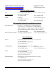
OMEGAnet On-line Service: http://www.omega.com Internet e-mail: info@omega.com Servicing North America: USA: ISO 9001 Certified Canada: One Omega Drive, Box 4047 Stamford, CT 06907-0047 Tel: (203) 359-1660 E-mail: info@omega.com 976 Bergar Laval (Quebec) H7L 5A1 Tel: (514) 856-6928 E-mail: info@omega.
United Kingdom: ISO 9002 Certified One Omega Drive, River Bend Technology Drive Northbank, Irlam, Manchester M44 5EX, England Tel: 44 (161) 777-6611 FAX: 44 (161) 777-6622 Toll Free in England: 0800-488-488 E-mail: info@omega.co.uk It is the policy of OMEGA to comply with all worldwide safety and EMC/EMI regulations that apply. OMEGA is constantly pursuing certification of it’s products to the European New Approach Directives. OMEGA will add the CE mark to every appropriate device upon certification.
Declaration of Conformity Manufacturer's Name: Omega Engineering Inc.
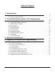
Table of Contents 1. Introduction ......................................................... 8 1.1 Installation . . . . . . . . . . . . . . . . . . . . . . . . . . . . . . . . . . . . . . . . . . . . . . . . . . . . . . . . 8 1.2 DAQ-16 Specifications . . . . . . . . . . . . . . . . . . . . . . . . . . . . . . . . . . . . . . . . . . . . . 9 2. Circuit Board Description and Configuration .............. 2.1 Analog to Digital Converter . . . . . . . . . . . . . . . . . . . . . . . . . . . . . . . . . . . .
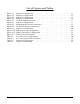
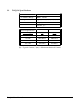
List of Figures and Tables Figure 2-1. Figure 2-2. Figure 2-3. Figure 2-4. Figure 2-5. Figure 2-6. Figure 2-7. Figure 2-8. Figure 2-9. Figure 2-10. Figure 2-11. Figure 3-1. Table 2-1. Table 2-2. Table 2-3. Table 4-1. Jumper J7 Configuration . . . . . . . . . . . . . . . . . . . . . . . . . . . . . . . . . . . . . . . . . . . . Jumper J6 Configuration . . . . . . . . . . . . . . . . . . . . . . . . . . . . . . . . . . . . . . . . . . . . Jumper J5 Configuration . . . . . . . . . . . . . . . . . . . . . . .
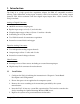
1. Introduction The DAQ-16 is a high speed data acquisition adapter for IBM AT compatible machines offering eight differential analog input channels with 16-bit resolution, two analog output channels with 12-bit resolution and four digital input/output lines. Other features of the DAQ-16 include: Analog to Digital Converter 100 KHz maximum sampling rate Bipolar input ranges of ±2.5, ±5, and ±10 volts Unipolar input ranges of 0 to +2.
1.2 DAQ-16 Specifications Bus Interface: ISA 16-bit I/O Address Range: 0000H - FFFFH Interrupt Levels: IRQ 2, 3, 4. 5, 6, 7, 10, 11, 12, 14, 15 DMA Levels: DRQ 5, 6, 7 DACK 5, 6, 7 Power Requirements: Power Supply I(t) I(ms) -5 volts --- --- +5 volts 1069.0 mA 1204.9mA -12 volts --- --- +12 volts 374.9 mA 491.
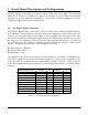
2. Circuit Board Description and Configuration The base address of the DAQ-16 is selected using switches SW1 and SW2. The operating mode of the DAQ-16 is controlled by jumpers J1 through J7, while DMA and interrupt selections are set with jumpers J8 through J11. Connections to external equipment are made through the high density 62-pin connector CN1. 2.1 Analog to Digital Converter The analog to digital (A/D) section of the DAQ-16 accepts up to 8 differential inputs from the D-62 connector.
Figures 2-1 and 2-2 show the configuration options for jumpers J7 and J6. J7 J7 J7 3 4 3 4 3 4 1 2 1 2 1 2 Gain = 1 Gain = 10 Gain = 100 Figure 2-1. Jumper J7 Configuration J6 J6 J6 4 5 6 4 5 6 4 5 6 1 2 3 1 2 3 1 2 3 10 volt range 5 volt range 2.5 volt range Figure 2-2.
The final stage of the A/D converter circuit is the A/D converter IC. The converter must be configured for unipolar or bipolar input voltages and for binary or 2's complement data conversion. These options are selected using jumper J5 as shown in Figure 2-3 below. J5 J5 4 5 6 4 5 6 1 2 3 1 2 3 Unipolar Bipolar J5 J5 4 5 6 4 5 6 1 2 3 1 2 3 Binary 2's complement Figure 2-3. Jumper J5 Configuration To simplify the following discussions, a new variable, Vmax, is introduced.
Voltage -Vmax -Vmax/2 0 +Vmax/2 +Vmax Binary unipolar n/a n/a 0 +32,768 +65,535 Binary bipolar 0 +16,384 +32,768 +49,152 +65,535 2’s Complement unipolar n/a n/a -32,768 0 +32,767 2’s Complement bipolar -32,768 -16,384 0 +16,384 +32,767 Table 2-2. A/D Conversion Format Examples In order to calculate the actual input voltage from the digital "code" provided by the DAQ-16, the user must know the configuration used to acquire the data.
2.2 Digital to Analog Converters The digital to analog (D/A) section of the DAQ-16 consists of two independent 12-bit multiplying D/A converters, and two independent two-stage output amplifiers. Digital data, (output to the D/A converter by the CPU), is converted to an analog voltage by the D/A converter, amplified by the output amplifiers and becomes output to the 62 pin connector at CN1. The D/A converters used on the DAQ-16 are 12-bit resolution converters.
5 6 7 8 J4 1 2 3 4 Channel 0 select Channel 1 gain Channel 1 select Channel 0 gain Figure 2-5. Jumper J4 Configuration Table 2-3 lists configuration options for jumper J4. Bipolar Unipolar Gain = 1 Gain = 2 Channel 0 connect 1-5 open 1-5 connect 2-6 open 2-6 Channel 1 connect 3-7 open 3-7 connect 4-8 open 4-8 Table 2-3.
2.4 Base Address The DAQ-16 uses 16 consecutive I/O address locations in the range 0 to 0FFFFH. Two six-position switches (SW1 and SW2) are used to select the base address. SW1 controls address lines A15 - A10, and SW2 controls A9 - A4. Address lines A3 - A0 are used internally by the DAQ-16 to select which register to access.
2.5 Clock Selection The DAQ-16 is equipped with a programmable clock circuit to produce data sampling rates independent from the clock rate of the host computer. An onboard 8254 programmable interval timer, with a 10 MHz clock input and either two or three cascaded 16-bit timers, provides the sampling rate. This enables the sampling rate to be adjusted from 10 us between samples to almost a year between samples, in as small as 100ns increments.
2.5.1 Internal Clock Sampling rates for the internal clock can be calculated using the following equation: t = 100ns * [N1*N2] or f = 10MHz / [N1*N2] where N1 is the low 16-bits of the clock divider and N2 is the high 16-bits of the clock divider. The following criteria must be met when selecting values for N1 and N2: 2 < N1 < 65,535 2 < N2 < 65,535 N1 * N2 > 100 Using the equations above, the minimum and maximum data sampling rates for the internal clock can be calculated.
When configured for a 48-bit divider, the first sampling period will be slightly longer than the others because the first clock period is required to load the initial value of the multi-function timer. The following equation calculates the additional time of the first period: t add = 100ns * [N1 * N2] To minimize the amount of additional time required for the first sample, select clock dividers such that N1 and N2 are as small as possible and N3 is as large as possible.
When the multi-function timer is used as a pre-divider, the frequency of the external clock input may be varied from DC to 10 MHz as long as the high portion of the clock is at least 30ns and the low portion is at least 50ns. Except for the first period, the sampling rate of the DAQ-16 will be the external clock frequency divided by the count value written to the multi-function timer.
2.7 Direct Memory Access Direct Memory Access (DMA) transfers provide a way of transferring data from the DAQ-16's A/D converter into the computer's memory without using the Central Processing Unit (CPU). DMA capability enables other system software to be executed while data is being input from the DAQ-16. The DAQ-16 actually implements two DMA channels. The advantage of having two DMA channels is that one channel can be transferring data while the second channel is being programmed.
2.8 Interrupts The DAQ-16 is capable of generating an interrupt from one of four sources: 1. End of conversion signal 2. DMA terminal count 3. Multi-function timer output 4. External interrupt input The interrupt source is software selected through the DAQ-16 control word register. The interrupt level is selected using the jumpers J10 and J11 as shown in Figure 2-11. J11 IRQ 7 IRQ 6 IRQ 5 IRQ 4 IRQ 3 IRQ 2 IRQ 10 IRQ 11 IRQ 12 IRQ 15 IRQ 14 J10 Factory default = IRQ 5 Figure 2-11.
3. External Connections The DAQ-16 is equipped with a high density 62-pin connector as shown in Figure 3-1.
CH0-,CH0+,...,CH7-,CH7+ : Analog inputs to the analog to digital converter. Amplitude and polarity depend upon jumper settings. The input resistance of these lines is 1.5K ohms typical. AOUT0, AOUT1: Analog outputs from the digital to analog converters. Polarity and maximum amplitude depend on the jumper settings and voltage references. Output resistance of the analog outputs is typically 70 ohms. VREF0, VREF1: External voltage references for the digital to analog converters. Input range is 0 to 5.
4. Register Description and Programming The DAQ-16 uses 16 consecutive I/O address locations in the range 0 to FFFFH. The card utilizes these addresses for the registers listed in Table 4-1. (* indicates registers located in 8254 counter).
DMAEN - enables / disables DMA. When set, logic 1, DMA transfers are enabled. DMACT - enables the multi-channel DMA capability of the DAQ-16. When set, logic 1, a terminal count on the active DMA channel causes DMA transfers to begin on the "stand-by" channel. When cleared, logic 0, DMA transfers halt when the terminal count is reached on the active channel. DMACH - indicates which of the DAQ-16's DMA channels is currently active to transfer data.
4.1.2 Start of Conversion Register The start of conversion register is 16-bit write only and performs two functions: 1. When configured for internal triggering, writing a "0" to this register generates the software trigger, starting the data conversion process. 2. Writing a "0" to this register at any time resets the VALID bit in the control word register. This allows the VALID bit to be reset at any time during the conversion process or before the event of an external trigger. 4.1.
4.2 Programming the 8254 Counter/Timer This section provides programming information for the 8254 counter/timer as implemented on the DAQ-16. For more details on the 8254, consult the Intel Micro-Processor and Peripheral Handbook. To program any of the counters contained in the 8254 counter/timer, three steps are required: 1. Write the configuration byte to the 8254 mode select/status register. This byte sets the operating mode of the selected counter. 2.
Counter 1 - Clock rate register (high word) operating mode: minimum count value: configuration byte: Example: 2 2 0 / 1 / 1 / 1 / 0 / 1 / 0 / 0 = 74H Program the value 13A4H into the high word of the clock rate register. output 74H to base_address + 0FH output A4H to base_address + 0DH output 13H to base_address + 0DH Example: Program the value FFFFH into the high word of the clock rate register.
DAQ-16 Users Manual Version 2.20 January 28, 1999 Part No.