
- Omega Data Acquisition Adapter Users Manual

2. Circuit Board Description and Configuration
The base address of the DAQ-16 is selected using switches SW1 and SW2. The operating
mode of the DAQ-16 is controlled by jumpers J1 through J7, while DMA and interrupt
selections are set with jumpers J8 through J11. Connections to external equipment are made
through the high density 62-pin connector CN1.
2.1 Analog to Digital Converter
The analog to digital (A/D) section of the DAQ-16 accepts up to 8 differential inputs from the
D-62 connector. These inputs pass through a dual 8-to-1 multiplexer circuit which selects the
channel to be converted. The selected input is then amplified and presented to the A/D
converter to be digitized. The digital output of the A/D is latched into a buffer to be read by
the computer. The multiplexer circuit selects one of the 8 differential channels to be input to
the A/D converter. The channel is software selected through the DAQ-16's control word
register. The typical characteristics of the multiplexer circuit are:
input resistance: 1.5 Kohm
switching time: 0.5 us
settling time: 3.5 us
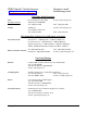
The amplifier stage of the A/D converter circuit performs two functions: (1) amplifies low
level input signals and (2) converts this input signal into a voltage range acceptable to the
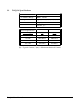
A/D converter. The amplifier circuit is controlled by jumpers J6 and J7. Table 2-1 below
shows the recommended jumper settings for various input voltage ranges, (* indicates factory
settings).
2-3, 4-5
2.5 v
1-3
100
+0.025/±0.025
1-2, 4-5
5 v
1-3
100
+0.05/±0.05
2-3, 5-6
10 v
1-3
100
+0.1/±.1
2-3, 4-5
2.5v
2-4
10
+0.25/±0.25
1-2, 4-5
5 v
2-4
10
+0.5/±0.5
2-3, 5-6
10 v
2-4
10
+1/±1
2-3, 4-5
2.5 v
3-4
1
+2.5/±2.5
1-2, 4-5
5 v
3-4
1
+5/±5
2-3, 5-6*
10 v
3-4*
1
+10/±10
---
---
---
---
Unipolar / Bipolar
J6
A/D Range
J7
Amplifier
Maximum Input Voltage
Table 2-1. A/D Converter Configurations
DAQ-16 Users Manual 10