User’s Guide Shop online at omega.com e-mail: info@omega.com For latest product manuals: omegamanual.
OMEGAnet® Online Service omega.com Internet e-mail info@omega.com Servicing North America: U.S.A.: ISO 9001 Certified Canada: One Omega Drive, P.O. Box 4047 Stamford, CT 06907-0047 TEL: (203) 359-1660 e-mail: info@omega.com 976 Bergar Laval (Quebec) H7L 5A1, Canada TEL: (514) 856-6928 e-mail: info@omega.ca FAX: (203) 359-7700 FAX: (514) 856-6886 For immediate technical or application assistance: U.S.A.
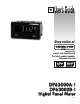
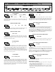
z FOUR SELECTABLE D.C. RANGES 200 µA, 2 mA, 20 mA, 200 mA z MINIMUM AND MAXIMUM DISPLAY CAPTURE z LCD, REFLECTIVE OR RED/GREEN LED BACKLIGHTING z 0.48" (12.2 mm) HIGH DIGITS C U L R z OPTIONAL SETPOINT OUTPUT MODULES US LISTED z OPTIONAL SERIAL COMMUNICATIONS MODULES (RS232 or RS485) IND. CONT. EQ.
GENERAL METER SPECIFICATIONS 1. DISPLAY: 5 digit LCD 0.48" (12.2 mm) high digits DP63000A-I: Reflective LCD with full viewing angle DP63000B-I: Transmissive LCD with selectable red or green LED backlight, viewing angle optimized. Display color change capability with output state when using an output module. 2. POWER: Input voltage range is +9 to +28 VDC with short circuit and input polarity protection. Must use a DP6-MLPS1 or a Class 2 or SELV rated power supply. MODEL NO.
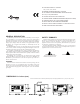
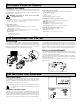
OPTIONAL PLUG-IN CARDS ADDING OPTION CARDS The DP63000 meters can be fitted with optional output cards and/or serial communications cards. The details for the plug-in cards can be reviewed in the specification section below. The plug-in cards, that are sold separately, can be installed initially or at a later date. DUAL SINKING OUTPUT CARD Type: Non-isolated switched DC, N Channel open drain MOSFET Current Rating: 100 mA max. VDS ON: 0.7 V @ 100 mA VDS MAX: 30 VDC Offstate Leakage Current: 0.5 mA max.
3.0 INSTALLING PLUG-IN CARDS The Plug-in cards are separately purchased option cards that perform specific functions. The cards plug into the main circuit board of the meter CAUTION: The Plug-in cards and main circuit board contain static sensitive components. Before handling the cards, discharge static charges from your body by touching a grounded bare metal object. Ideally, handle the cards at a static controlled clean workstation. Also, only handle the cards by the edges.
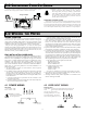
4.3 INPUT WIRING CAUTION: Power input common is NOT isolated from user input common. In order to preserve the safety of the meter application, the power input common must be suitably isolated from hazardous live earth referenced voltage; or input common must be at protective earth ground potential. If not, hazardous voltage may be present at the User Inputs and User Input Common terminals.
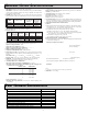
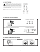
5.0 REVIEWING BUTTON THE FRONT BUTTONS AND DISPLAY DISPLAY MODE OPERATION ENTERING PROGRAM MODE PROGRAMMING MODE OPERATION SEL Index display through enabled values Press and hold for 2 seconds to activate Store selected parameter and index to next parameter RST Resets values (MIN/MAX) or outputs Advances through the program menu Increments selected parameter value or selection OPERATING MODE DISPLAY DESIGNATORS “1” - To the right of the display indicates setpoint 1 output activated.
6.1 MODULE 1 - SIGNAL INPUT PARAMETERS (1-INP) PARAMETER MENU SCALING STYLE INPUT RANGE rAN6E ª « 0.02A SELECTION 200uA 0.002A RANGE RESOLUTION SELECTION 200.00 µA 0.02A 0.2A 2.0000 mA StYLE RANGE RESOLUTION ª 20.000 mA 200.00 mA « KEy APLY KEy If Input Values and corresponding Display Values are known, the Key-in (KEY) scaling style can be used. This allows scaling without the presence or changing of the input signal.
USER INPUT FUNCTION USrIN « ª NO DISPLAY MODE NO P-Loc ZErO rESEt DISPLAY MODE DESCRIPTION No Function User Input disabled. Program Mode Lock-out Zero Input (Edge triggered) Reset (Edge triggered) See Programming Mode Access chart (Module 3). Zero the Input Display value causing Display Reading to be Offset. Resets the assigned value(s) to the current input value.
6.3 MODULE 3 - DISPLAY AND FRONT PANEL BUTTON PARAMETERS (3-dSP) PARAMETER MENU DISPLAY UPDATE TIME dSP-t ª « 1 DISPLAY COLOR (BACKLIGHT UNIT ONLY) 1 0.5 2 seconds COLOr ª This parameter sets the display update time in seconds. « rEd rEd 6rn Enter the desired display color, red or green. This parameter is active for backlight units only.
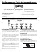
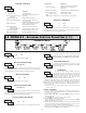
6.4 MODULE 4 - SETPOINT OUTPUT PARAMETERS (4-SPt) PARAMETER MENU The Setpoint Output Parameters are only active when an optional output module is installed in the meter. SETPOINT VALUE SPt-n « ª 10000 SETPOINT SELECT SPSEL « ª NO NO SP-1 ª NO YES 99999 HYSTERESIS VALUE HYS-n ª « 1 to 59999 2 Enter desired hysteresis value. See Setpoint Output Figures for visual explanation of how setpoint output actions (balanced and unbalanced) are affected by the hysteresis.
OUTPUT RESET WITH DISPLAY RESET button or user input manual reset, serial reset command or meter power cycle. When the user input or RST button is activated (momentary action), the corresponding “on” output is reset immediately and remains off until the trigger point is crossed again. (Previously latched alarms will be off if power up Display Value is lower than setpoint value.) « rEn-n ª NO YES YES This parameter enables the RST button or user input to reset the output when the display is reset.
Press and hold SEL button to enter Programming Mode.
WARRANTY/DISCLAIMER OMEGA ENGINEERING, INC. warrants this unit to be free of defects in materials and workmanship for a period of 13 months from date of purchase. OMEGA’s WARRANTY adds an additional one (1) month grace period to the normal one (1) year product warranty to cover handling and shipping time. This ensures that OMEGA’s customers receive maximum coverage on each product. If the unit malfunctions, it must be returned to the factory for evaluation.
Where Do I Find Everything I Need for Process Measurement and Control? OMEGA…Of Course! Shop online at omega.