User’s Guide Shop online at omega.com e-mail: info@omega.com For latest product manuals: omegamanual.
OMEGAnet ® On-Line Service omega.com Internet e-mail info@omega.com Servicing North America: Canada: 976 Bergar Laval (Quebec) H7L 5A1, Canada Tel: (514) 856-6928 FAX: (514) 856-6886 e-mail: info@omega.ca U.S.A.: ISO 9001 Certified One Omega Drive, Box 4047 Stamford, CT 06907-0047 Tel: (203) 359-1660 FAX: (203) 359-7700 e-mail: info@omega.com For immediate technical or application assistance: U.S.A.
User’s Manual DRF Series INDEX GENERAL INFORMATION.................................................. 4 QUICK GUIDE .................................................................... 5 POWER SUPPLY CONNECTIONS ................ 5 SIGNAL ADJUSTMENT .................................. 6 and 7 DIMENSIONS AND CONNECTIONS .............. 8 TECHNICAL DATA .............................................................. 9 INPUT SIGNAL ............................................... 9 OUTPUT SIGNAL ...................
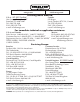
User’s Manual DRF Series GENERAL INFORMATION The DRF series of Isolated Signal Converters, allow to convert process signals, temperatures, electrical signals, etc, to current loops or voltage signals for further retransmision, while introducing into the system galvanic isolation barriers between the input, the output and the power supply circuits. The DRF series of Isolated Signal Converters, offer an excellent relation between signal conversion speed and measurement accuracy. Offering up to a 0.
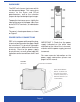
User’s Manual DRF Series QUICK GUIDE The DRF units have a front cover which can be opened down. This cover gives access to the Span and Offset potentiometers, and to the selection jumpers for input and output signal ranges. To open the front cover, press slightly the sides of the cover at the upper side, close to the OUTPUT terminals, as indicated on Figure1. The cover is free to open down, as shown on Figure2.
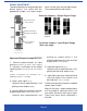
User’s Manual DRF Series SIGNAL ADJUSTMENT To proceed to adjust a range of input and output signals, first select with the appropriate jumpers, the signal ranges which include your desired adjustment. Then proceed to the adjustment.
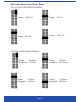
User’s Manual DRF Series SELECTION JUMPERS : I NPUT SIGNAL RANGE DRF-POT for POTENTIOMETER SIGNALS Range : 100% FS Range : 25% FS Range : 12.5% FS Range : 50% FS DRF-RES for RESISTANCE SIGNALS Range : 10 KOhms Range Min : 5 KOhms Range : 3 KOhms Range Min : 1.5 KOhms Range : 1.
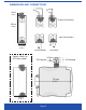
User’s Manual DRF Series DIMENSIONS AND CONNECTIONS 9mm (0.35’’) Output Connections 93mm (3.66’’) Input Connections 22,5mm (0.89’’) POTENTIOMETER Special Width for AC Power models DC Powered RESISTANCE 24 Vdc ~ 0 Vdc ~ 110 mm (4.33’’) 37mm (1.
User’s Manual DRF Series TECHNICAL DATA : Models DRF-POT and DRF-RES INPUT SIGNAL for POTENTIOMETER RANGES 0/100 % 0/50 % 0/25 % 0/12.5% (minimum 8%) Potentiometer value min 100Ohms max 1MOhm 3 Wire System, 1 Vdc Excitation Standard DIN rail mounting, as specified on DIN46277 and DIN EN 50022 37.5 x 7.5 mm (1.38 x 0.3 ´´) GALVANIC ISOLATION LEVELS DC Units Input - Output 3.5 KV (60 seconds) Power-Input 3.
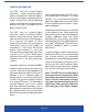
User’s Manual DRF Series CAUTIONS, WARNINGS AND NOTES INSTALATION PRECAUTIONS.- The installation and the future use of this unit must be done by qualified personnel. The unit has not AC (mains) switch, neither internal protection fuse. It will be in operation as soon as power is connected.
WARRANTY / DISCLAIMER OMEGA ENGINEERING, INC. warrants this unit to be free of defects in materials and workmanship for a period of 13 months from date of purchase. OMEGA’s Warranty adds an additional one (1) month grace period to the normal one (1) year product warranty to cover handling and shipping time. This ensures that OMEGA’s customers receive maximum coverage on each product. If the unit malfunctions, it must be returned to the factory for evaluation.
Where Do I Find Everything I Need for Process Measurement and Control? OMEGA…Of Course! Shop online at omega.