Table of Contents Introduction ..........................................................................................................................................iii • Terms used in this Manual ........................................................................................................... iii • Product Symbols .......................................................................................................................... iii Operator Safety Information .........................
3.0 SET-UP ........................................................................................................................................... 18 3.1 POWER CONNECTION ..........................................................................................................18 3.1.1 BATTERY INSTALLATION .............................................................................................18 3.1.2 CONNECTING THE AC POWER ADAPTER ................................................................
Introduction This User’s Guide explains how to use OM-550. This manual is written for users of varied experience. If a section covers information you already know, feel free to skip to the next section. • Terms used in this Manual In this manual, the following definitions are used for special terms and symbols. • Informs the user that the note identifies conditions or practices that could result in personal injury or damage to property other than the equipment.
Operator Safety Information The safety information in this summary is for the benefit of operating personnel. Warnings and Cautions will also be found throughout the manual where they apply. PRODUCT USAGE WARNINGS: For fire and electric shock protection, DO NOT connect the input channels to objects at elevated electrical potential.
For protection of the OM-550 itself, observe the following: • Do not immerse the OM-550 in liquids. • Do not subject the OM-550 to sharp impacts or drops. • Do not expose the OM-550 to corrosive environments. • Extended exposure to temperatures below the specified minimum may damage the battery (optional external rechargeable battery pack only). • Extended exposure to temperatures above the specified maximum may damage the OM-550 itself or its optional external rechargeable battery pack.
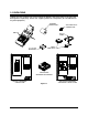
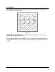
1.0 UNPACKING Unpack the unit carefully. Be sure to check for options and accessories that may have been packed separately. Retain the shipping carton for reshipment (for recalibration or any other purpose). THERMAL PAPER ROLL OM-550 VOLTAGE INPUT CONNECTOR RS-232 CABLE CABLE ADAPTERS (4) 1.
2.0 FEATURES This section explains the Features for the OM-550 System and optional items. 2.
2.1.1 ACTIVITY LED & HORN The Activity LED and internal horn provide a quick indication of the unit's status. For example a short, periodic beep and flash indicates that the OM-550 is “ON” but not being programmed. The horn produces two different sounds, a beep and blat. Valid key closures produce the beep sound and invalid keys produce the blat. For example, the OK key is only used in programming. Pressing the OK key when not programming will produce a blat sound.
2.1.2 KEYPAD The Keypad has more than one function and many are self-evident, so only the main key functions are discussed here. Figure 2-4 The ON-OFF and PROG/EXIT keys are toggles. They are often discussed here by separate function to avoid confusion. For example, the ON key and the OFF key are the same key but its function changes (toggles) between “ON” and “OFF”. All keys but the ON key are disabled when the unit is “OFF”.
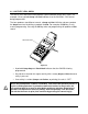
• ON-OFF The ON-OFF key activates the OM-550. If the unit is “OFF”, pressing the ON key will activate it, light the Activity LED and beep the horn. When the key is released, the unit will print the key name, time, date, and a command menu: KEY NAME MENU Figure 2-5 If the OM-550 is “ON”, pressing the OFF key will cause it to print: Figure 2-6 ... then deactivate. It will remain “OFF” until the ON key is pressed.
• RUN The RUN key activates the OM-550 to begin logging. The data is stored in internal memory, optionally printed, and can be transferred to a PC at a later time. When the RUN key is pressed, the messages shown in Figure 2-8 are displayed.
• STOP Once logging is started, it will continue until the STOP key is pressed, the unit is deliberately turned “OFF”, or the batteries are exhausted. The OM-550 can also be programmed to automatically stop logging when the data cache if full. To stop logging, first ensure that the unit is “awake”, then press the STOP key. (If the unit is in Power save mode, press ON and then the STOP key instead.) The unit will complete the current scan but logging is now disabled and the Statistics will be printed.
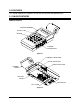
2.1.3 CHANNEL CONNECTORS The five input connectors on the right side of the OM-550 accept either voltage or thermocouple inputs values. Figure 2-9 The mating connectors are color coded by conductor material, as described in the table below. For best accuracy, use the appropriate color of connector.
2.1.4 PRINTER WINDOW The OM-550 has a protective viewing window that can be removed to clear paper jams, or to allow closer inspection of the print head & paper path. To remove the Viewing Window: 1. Lift under the bottom edge to a 45-degree angle, then pull it away from the case, as shown in Figure 2-10: Figure 2-10 2. Replace the window by reversing the removal sequence making sure the tabs click into place. The window material is very durable but may be scratched by abrasives.
2.1.5 THERMAL PAPER Two thermal paper rolls are supplied for printing logged and programming data. The paper is placed on the paper bail with the active side of the paper-inserted face down into the rear paper feed slot. Refer to section 3.2 PAPER INSTALLATION for more information. 2.1.6 BATTERY COVER Four AA Batteries are supplied in the kit that must be installed prior to operation. The Battery cover is located on the bottom side of the OM-550.
2.1.9 GAIN ADJUST The Gain Adjust holes are used when performing a Voltage or Temperature calibration procedure. There are two holes located on the bottom of the OM-550 one for adjusting the Volt Gain and another for adjusting the Temp Gain (see APPENDIX A: CALIBRATION for more information). 2.1.10 TILT STAND The Tilt Stand to allows the user to get a better view of the Keypad and printed data.
2.2 POWER SUPPLIES As previously discussed the OM-550 operates from four AA internal batteries, AC power adapter, DC power cable or an external rechargeable battery pack. Prior to use, always ensure that external power supplies are operating properly before connecting them to the OM-550. • The AC Power Adapter plugs into an appropriate 120V AC (in North America) power outlet and then the DC power plug is inserted into the DC Jack on the left side of the unit.
2.3 INPUTS As previously discussed, the OM-550 accepts either voltage or thermocouple inputs. The Signals discussed in this section are input through one of the channel connectors on the right side of the OM-550. 2.3.1 VOLTAGE (TRANSDUCER) INPUTS The Voltage connector used for inputs is a white connector with copper pins. Figure 2-13 2.3.2 PROBES Optional Voltage and Current probe sets are available for the OM-550.
2.3.3 THERMOCOUPLE INPUTS Use a connector of the appropriate color, by thermocouple (T/C) type, as explained previously.
2.4 PROGRAMMED FEATURES There are special programmed features that support the operation of the OM-550. These features are described in the following sections. 2.4.1 DATA CACHE The OM-550 contains a 28 Kbyte data cache that retains its data even when the unit is “OFF”. Each data point occupies four bytes of cache memory; thus the capacity of the cache depends upon the quantity of active (unskipped) channels.
2.4.2 STATISTICS When the STOP key pressed after a data run, the Statistics are then printed. This printout shows the date, time, number of samples taken (N), and the minimum, average, and maximum values (by channel) of the data presently stored in the cache: Figure 2-15 If "******" appears on the tape, as shown in Figure 2-15, the value stored in cache memory is not printable.
2.4.3 POWER-SAVE MODE When logging data, the OM-550 prolongs its battery life by automatically turning “OFF” (power-save mode) when unattended (no key closures detected for about 1 minute). If the OM-550 is in RUN mode it will wake and log data at the next appropriate time. When the OM-550 is in the Programming and CAL modes it remains “ON”; and must be turned “OFF” manually. 2.4.
3.0 SET-UP This section provides the necessary information to set the OM-550 up for proper operation. 3.1 POWER CONNECTION As previously discussed there are several options to supply power to the OM-550 and the following sections explain how to use them. 3.1.1 BATTERY INSTALLATION Slide the battery cover open and insert the batteries as shown below. Replace the cover and turn the unit “ON: by pressing the ON-OFF key. The OM-550 will then activate and initiate printer activity.
3.1.2 CONNECTING THE AC POWER ADAPTER Plug the AC Power Adapter into an appropriate 120V AC (in North America) power outlet. Insert the adapter's connector into the receptacle on the left side of the unit. The OM-550 is now ready to operate on external power. The OM-550 will operate without batteries but data may be lost if the power fails or the AC Power Adapter is accidentally removed. It is recommended when operating OM-550 the batteries are installed first.
3.2 PAPER INSTALLATION 1. Unwind several inches of paper from the paper roll. 2. Fold the end of the thermal paper over creating a straight flat edge as shown in Figure 3-2. This creates a strong edge and allows the paper properly center in the printer when inserting it into the rear paper slot. Paper orientation is very important because only one side is coated for thermal printing. Figure 3-2 3. Insert the paper into the rear paper slot as shown in Figure 3-2.
3.3 DATA PORT CONNECTION Prior to transferring data, the OM-550 must be connected to a PC with the RS-232 cable assembly supplied with the kit. The cable assembly includes a telephone-style cable and two adapters. The OM-550 for Windows software supplied with the kit is used to transfer data through the OM-550 RS-232 Port to a PC for analysis and storage. 9 PIN ADAPTER 25 PIN ADAPTER Figure 3-4 The cable is fitted with a 4P4C connector for the Data Port on the OM-550 and a 6P4C connector for an adapter.
4.0 PROGRAMMING When prior to operating the OM-550 it must first be programmed. This section covers all of the programming options available. All programmed settings but the time & date are stored in EEPROM and retained even if the batteries are removed. • Programming outline: 1.
4.1 PROGRAMMING KEYS Pressing the PROG key activates the Program mode. The unit immediately prints the current programming information and prompts the user to select a channel to reprogram: CURRENT TIME AND DATE LOG INTERVAL AND REJECTION FREQUENCY DATA CACHE INFORMATION ONLY TWO CHANNELS ARE ACTIVE THE PROGRAM COMMAND A #KEY, OK, OR EXIT MUST BE PRESSED. Figure 4-1 Channels may be defined as Voltage, Temperature (T/C) or Skipped.
4.2 PRINT FORMATTING When a Voltage channel (or the Math) channel is programmed, the OM-550 prompts the user for a decimal point position (or decimal point fix). This number between 0 and 5 is the location of the decimal point in the print field. POSITION 5 4 3 2 1 0 INTERPRETATION .##### #.#### ##.### ###.## ####.# #####. EXAMPLE .00001 0.0001 00.001 000.01 0000.1 00001. Any five-digit data value between "±.00000" and "±99999" can be printed.
4.3 TEMPERATURE CHANNELS Any of the five channels can be programmed as Temperature channels. The user may select one of the four standard thermocouple types: J, K, T, or E and three optional types: B, S, or R. The Thermocouple types can be mixed. For example, channel #1 with a Type E thermocouple and channel #2 with a Type J thermocouple may be used. Temperature channel data is calculated, saved and printed in the temperature units currently selected (°C or °F).
4.5 MATH PSEUDO-CHANNEL The OM-550 has five physical channels and a sixth "channel" that can display the result of a math operation involving any two of the other channels (or a single channel, twice). The channels chosen as a basis for the Math channel are its "constituents". The Math channel can be activated or "skipped" during programming. Math channel data will be printed only (not stored to RAM) if it and both constituent channels are active (not skipped).
4.6 LOG INTERVAL The each active channel is scanned once during each log interval. The Log Interval is the time between readings, expressed in HH:MM:SS (hours:minutes:seconds). It can be programmed from one second to one day (00:00:01 to 23:59:59). The Keypad has no colon key, so enter the log interval as six numbers and the colons will automatically be inserted. The interval can be set much faster than it can print it.
4.7 OPERATION AT FULL CACHE (RECORDING TIME) The OM-550 includes a battery-backed, 28-Kb data cache. The cache is erased when the RUN or PROG keys are pressed and new data is stored during logging. The OM550 can be programmed to stop when the data cache is full or to log continuously and overwrite the oldest data when the cache fills. When the RUN key is pressed, the selected operation and the time required to fill the cache is displayed.
4.8 DATE The current date is entered during programming and is kept in a real-time clock that is backed by the AA batteries. The clock will then be accurate unless the batteries are removed or a Manual Reset is executed. The Keypad has no colon key, so enter the date as six numbers and the colons will automatically be inserted as necessary. 4.9 TIME The current time is entered during programming and kept in real-time clock that is backed by the AA batteries.
4.12 CALIBRATION MODE The OM-550 includes a Cold-Junction Compensation network server that is automatically disabled during temperature calibration. Calibration mode temperature measurements performed in the usual manner will appear abnormal with the OM-550 in the CAL mode. When the OM-550 is in the CAL mode, the time and date are printed with additional characters: UNUSUAL FORMAT DENOTES CAL MODE Figure 4-7 To return to Normal mode: • Turn the unit “OFF”, then back “ON”.
4.13 TADJUST Tadjust is a cumulative value set during programming and summed with each Temperature channel's data during logging. It is cleared to a value of +00.0 at Manual Reset and on entry to the CAL mode. Use Tadjust to correct temperature readings for batch variances in thermocouple wire or to align the readings with another measurement device. Tadjust is programmed differently from other values because its use is different. The Tadjust value is cumulative. When a value of +0.
4.14 VOLTAGE INPUT SCALING Any of the input channels (1 through 5) may be programmed as Voltage channels. Each Voltage channel includes unique m and b constants for "scaling" data to your application. These constants default to +1.00000 and 000000, respectively, when the channel is first programmed as a Voltage channel but the user may reprogram them as necessary. The following pages include examples for common transducers. 4.14.
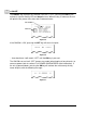
4.14.3 MATCHING A CURRENT TRANSDUCER Use one resistor to develop the necessary voltage at the input: I + TRANSDUCER OUTPUT R1 V OM-550 INPUT Figure 4-9 V = OM-550 maximum input voltage = 2.0000 VDC = R1 * I I = 1/2 transducer's maximum output current R1 = 2 / I The 4-20 mA Current Probe uses this technique (with R1=100 Ω ) to convert a 4-20 mA current to a 0.4-2.0 VDC signal.
4.14.4 DATA SCALING (mX + b calculation) The output voltage of a properly matched transducer can be read the but the data will be in "volts" and the user might prefer data in units that reflect the application. Programming the OM-550 to produce data in terms of the actual parameter being measured is called Scaling. The linear slope-intercept formula (Y = mX + b) makes this possible.
4.14.5 MATCHING AND SCALING A VOLTAGE TRANSDUCER EXAMPLE: Given a 20 - 90 % RH (Relative Humidity) transducer with a 0 - 10 VDC output at a maximum current of 3 mA. Program the OM-550 to indicate 20.00 %RH to 90.00 %RH (that is, to indicate %RH with 0.01% resolution). If a ±10 Voltage Probe is being used, begin with step 3, below. (This probe is already matched to the OM-550). 1. First, find the Matching resistors: I = = = 1/2 maximum current 0.003 / 2 0.0015 Amps R1 = = = 2/I 2 / 0.
3. Next, find m & b: X1 = = 0 VDC 0 A/D counts ç minimum expected input at Transducer minimum output X2 = = 2.0000 VDC 20000 A/D counts ç maximum allowable input at Transducer maximum output Y1 = = 20.00 %RH 2000 display counts ç choose decimal point = 2 Y2 = m = = = 90.00 %RH 9000 display counts = (Y1 - Y2) / (X1 - X2) (2000 - 9000) / (0 - 20,000) 0.35000 ç keep decimal point = 2 [Desired % RH resolution 2 places to right of the decimal point (.01% RH)] b= = = Y2 - (m * X2) 9000 - (0.
4.14.6 MATCHING AND SCALING A CURRENT TRANSDUCER Example: Given a 0 - 150-PSI transducer with a 4-20 mA output. Program the OM-550 to indicate 0 - 150 PSI with 0.01-PSI resolution. If the 4-20 mA Current Probe is being used, begin with step 2, below. (This probe is already matched to the OM-550). 1. First, find the Matching resistor: R1 = = = = 2/I 2 / 20 mA 2 / 0.02 100 Ω When the transducer output is 4 mA, the OM-550 will see 0.4 VDC and when the transducer output is 20 mA, the OM-550 will see 2 VDC. 2.
3.
4.15 UNIT LABELS Each channel includes a character Unit label. The Unit label is assigned during programming and printed with the data for that channel during logging. All Temperature channels use one, common label (°C or °F). Refer to section 4.10 TEMPERATURE UNITS for more information. Each Voltage channel may be programmed with an individual Unit label and every available label has an associated number.
5.0 OPERATION The following section will guide the user through a typical logging process. These steps may vary depending on the type of data the user is logging. When using this procedure it may be necessary to refer to section 4.0 PROGRAMMING for proper programming procedures and alternate options. 1. Turn the OM-550 “ON”. 2. Press the PROG key to confirm the current programming information.
3. Enter the desired Log Interval time, or press OK to advance to the next item. Figure 5-3: Log Interval Time 4. Select whether to stop collecting data when the Cache is full, collect data continuously, or press OK to advance to the next item. OR Figure 5-4: Operation at Full Cache 5. Enter the current Time, or press OK to advance to the next item.
6. Enter the current Date, or press OK to advance to the next item. Figure 5-6: Current Date 7. Select the desired temperature units, or press OK to advance to the next item. OR Figure 5-7: Temperature Units 8. Select the Rejection frequency, or press OK to advance to the next item.
9. Turn the Cal mode ON, OFF, or press OK to advance to the next item. OR Figure 5-9: Cal Mode Selection 10. Enter a Tadjust value, or press OK to finish programming. Figure 5-10: Tadjust Value Selection • Programming is now complete and the list of functions will be printed.
11. Press the RUN key and the OM-550 will print the log interval, stop time and prompt the user to choose if they want to print the data while logging. When either YES or NO is selected the data collection process automatically begins. Figure 5-11 12. When the data collection process is complete the data stored in the internal cache can now be transferred to a PC. 13. Connect the RS-232 cable to the Data port on the OM-550 and make sure the other end is connected to the PC (refer to section 3.
APPENDIX A: CALIBRATION • MANUAL RESET A Manual Reset returns the OM-550 to a "known" condition. This is useful when troubleshooting or learning to program the unit. A Manual Reset programs the OM-550 as follows: • CH1 is a Voltage channel, m=1.00000, b=000000, dp=4, units = (63) "V". • CH2 is a Type K thermocouple Temperature channel. • CH3 through 5 are Skipped • CH6 is Skipped but defined as CH4+CH5, decimal fix=1, units = .00 (Blank) • The Temperature Units for all temperature channels are °C.
• CALIBRATION PROCEDURE Using the following Calibration procedure we recommend that the OM-550 is recalibrated every 6 months. Setup: 1. Perform a Manual Reset 2. Press the PROG key to enter the programming mode 3. Expect a printout similar to the following: Figure A-2 4.
• VOLTAGE ADJUSTMENT PROCEDURE: It is recommended that the OM-550 is operated with the batteries while this procedure is preformed to reducing noise in measured voltages. 1. Use a white (copper) voltage connector and copper wire for all voltage and thermocouple inputs during calibration. 2. Locate the access hole for the Volt Gain adjustment on the bottom of the OM550. GAIN ADJUST Figure A-4 3. Apply a 2.00000 VDC standard voltage to channel #1. 4.
• EXITING CAL MODE When calibration is complete, the unit is still in the CAL mode (it is ignoring the cold junction compensation). To return to normal operation: • Press PROG on the keypad to enter the programming mode, then use the OK key to step down through the menu to the Calibration prompt, and then answer NO. Figure 6-1 OR • Turn the unit “OFF” (and back “ON” if desired). OR • Perform a Manual Reset.
APPENDIX B: SPECIFICATIONS (OM-550 at 25°C unless otherwise stated) VOLTAGE MEASUREMENT INPUTS: IMPEDANCE: RANGE: RESOLUTION: ACCURACY: CMRR: NMRR: ABSOLUTE MAXIMUM OVERVOLTAGE PROTECTION: THERMOCOUPLE INPUTS: TYPES: RESOLUTION: INPUT IMPEDANCE: LEAD RESISTANCE EFFECT: COLD JUNCTION COMPENSATION: CMRR at 50/60 Hz: NMRR at 50/60 Hz: ACCURACY: TYPE RANGE (°C) J -165. to +760. 0. to +760. K -101. to +1250. 0. to +1250. T -105. to +400. 0. to +400. E -140. to +660. 0. to +660.
PRINTER TYPE: PAPER ROLL CAPACITY: LINE HEIGHT: LINES PER ROLL: PAPER LIFE (Printing 5 channels every 10-min.) DIGITAL INTERFACE (RS-232) COMMUNICATION FORMAT: OUTPUT VOLTAGES: A/D CONVERSION RESOLUTION: TECHNIQUE: CHANNEL CAPACITY NUMBER OF INPUT CHANNELS: INTERNAL DATA STORAGE MAXIMUM CAPACITY: ENVIRONMENTAL OPERATING AND STORAGE ENVIRONMENT: OPERATING TEMPERATURE RANGE: STORAGE TEMPERATURE RANGE: OPERATING RELATIVE HUMIDITY RANGE: 24-Column Thermal 82 ft ±1.6 ft 0.
POLLUTION DEGREE: Pollution Degree 2 per IEC Publication 664 This classification means that normally only non-conductive pollution (in the form of dust) occurs. Occasionally, however, a temporary conductivity caused by condensation must be expected. INSTALLATION CATEGORY (OVERVOLTAGE CATEGORY): Installation Category II per IEC publication 664 This classification applies to products used on electric supply branch circuits.
OM-550 DOS Software
TABLE OF CONTENTS INTRODUCTION.....................................................................................................................................ii Ÿ How to Use This Manual ............................................................................................................... ii Ÿ Terms Used in this Manual ........................................................................................................... ii Ÿ Fonts Used in this Manual.......................................
INTRODUCTION This Software User’s Guide explains how to use Omega’s OM-550 DOS software. The software requires an IBM PC or compatible, with 640K of ram and 1 or 2 serial ports. The software is supplied on a 3 ½” disk, and it is recommended that at lease one backup copy is made to hold in reserve. Refer to your computer manual for copying instructions. OM-550 data can be saved to disk as experiment files. The files are automatically named with the word LOG, followed by three numbers, like LOG007.
Ÿ Fonts Used in this Manual This manual uses a special font to indicate terms or words that can be found directly on the PC display. For Example: The Master Menu options change to match what you are doing. This font indicates the words Master Menu are actually found in the PC display. Ÿ File Formats Data transferred from the OM-550 to a PC can be stored to disk in two file formats: Experiment files (LOG###.BIN) are stored in binary format to conserve disk space.
PC Hardware Requirements Before OM-550 DOS software can be used, a 386 or better computer will be required to run the software. Specific recommendations are as follows: CPU, RAM, Hardware: 386 640K RAM (minimum). 400KB of free disk space. Disk Drive: 3.5” high-density floppy disk drive. Mouse: IBM compatible mouse, plugged into either a dedicated mouse or serial port. Serial Port: At least one port in addition to the one used for the mouse.
Software Installation The software is on a 3.5” floppy disk and before it is installed on a PC, make a backup copy of the program disk, you should never work from your original program disks. Be sure to view the README file on the program disk before installing the software (any standard text viewer can be used). The README contains the latest information on the software and installation instructions. • HARD DRIVE INSTALLATION 1. Insert disk 1 in the disk drive. 2.
1.0 STARTING THE PROGRAM To start the program: 1. At the DOS prompt type the DOS command, CD (change directory), drive name, colon, backslash and the program name and hit the [enter] key. For example, if the program in installed in the default directory C:\M50 type: • CD C:\M50\M50C (If you have a computer with a CGA video card). • CD C:\M50\M50E (If you have a computer with a EGA video card). • CD C:\M50\M50V (If you have a computer with a VGA video card).
2.0 MASTER MENU The Master Menu lists the options available to assist the user to read data from the OM550, read an existing experiment file, or modify the software configuration parameters (custom labels and computer configuration). The following sections will describe how each option will assist the user to analyze the data collected by OM-550. Experiment file LOG001 is always automatically loaded when the program is started and is the file used in all the figures in this manual.
2.1 READING DATA FROM THE OM-550 Option #1 Reading Data from the OM-550, on the Master menu allows the user to transfer the data from the OM-550 to the PC. Before starting the read process, the communication cable must be installed and the OM-550 is ON. To transfer data: 1. Press the key and instructions how to properly transfer data will appear on the screen. Data Transfer Screen 2. Press any key to start transferring data and the number of bytes being moved will appear on the screen.
2.2 LOAD EXISTING LOG FILES Option #2 Load Existing LOG Files, on the Master menu allows the user to load saved LOG files into the software program. To load a LOG file: 1. Press the key and a list of saved experiment files will appear. The list includes the Log Interval used to acquire the data, the Date and Time when the last datapoint in the file was taken, the Number of data points in the file, and the Optional Plot Title assigned to the file (user configurable). Log Files Screen 2.
2.3 MODIFY SOFTWARE CONFIGURATION Option #3 Modify Software Configuration, on the Master menu allows the user to configure the system by selecting the serial port, printer, print orientation, company name, and next file number. The choices made using this option will be automatically saved in a file named M51.CON when this screen is exited. To make changes: 1. Press the key and a list of configuration items will appear. Software Configuration Screen 2.
• Select the PC COM: # (serial interface port #) that will be used to transfer data from the OM-550 to the computer. The available ports are COM1 and COM2. • Select a Printer type, supported printers fall into one of four groups. See the README file for more details. • Select paper orientation of printed data (Portrait or Landscape). • Enter a Company name that will be included when you Print the data, List or save it as a Text file.
2.4 LIST DATA ON MONITOR Option #4 List Data on Monitor, on the Master menu allows the user to view the experiment data in columnar format. To list data: 1. Press the key and experiment data will start scrolling vertically across the screen. To stop or start the data, press the Spacebar at any time. To increment individual data points one at a time, press an arrow key once. Listing Data 2. Press the [esc] key when finished viewing data.
2.5 PRINT DATA ON PRINTER Option #5 Print Data on Printer, on the Master menu allows the user to print the data in columnar format on the selected printer as discussed in section 2.3 MODIFY SOFTWARE CONFIGURATION. To print data: 1. Press the key and the printing process will automatically start, when the data is done spooling the software will automatically return to the Master Menu. 2.
2.7 EDIT PLOT LABELS Option #7 Edit Plot Labels, on the Master menu allows the user to choose Plot Labels for any OM-550 channel. Plot Labels are text on the Hot Plot graph to identify the data from each individual channel, the graph Title or other notes about the data. For example, Channel 1 might be labeled as “Boiler Room Temperature”. The label would be displayed near the channel 1 description on the Hot Plot screen. To edit a plot label: 1. Press the key and the Plot Label screen will appear.
2.8 HOT PLOT Option #8 HOT PLOT, on the Master menu plots the experiment data in a graphical format and allows the user analyze the data. The HOT PLOT screen is designed for use with either a mouse or a keyboard and this manual describs the functionality for both.
2.8.1 STATUS BAR The top of the Hot Plot shows the File Name, Plot Title, and Time Stamp/X-Y Readout. FILE NAME PLOT TITLE TIME STAMP/ X & Y READOUT Status Bar • The File name is the name of the currently loaded experiment file. If the current experiment data is not saved the file name will read “?????” in this location. • The Plot Title is the entry specified by the user using the Edit Plot Labels option (See section 2.7 EDIT PLOT LABELS for details).
2.8.2 MAGNIFY TOOL The Magnify tool enlarges any selected area of the graph for easy visual examination. To Magnify a portion of the Data Graph: 1. Click the Magnify tool. A message box will appear below the Magnify Tool informing the user to: “Click and drag to select area”. 2. Position the mouse pointer to select one corner of the desired area to enlarge. 3. Press the left mouse button and drag the pointer diagonally to the opposite corner of the box. An outline of the box appears as you drag. 5.
When using the Magnify tool, the Magnify Map indicates the area being magnified with red box drawn around the area currently being magnified. If the data graph was previously magnified, the current level of magnification is displayed as the smallest red box (Previous magnified areas are noted with a white outlined box). MAGNIFY MAP MAGNIFIED AREA To return to the full view, click the Magnify Map outside of the magnified area.
2.8.3 Y-AXIS LABELS The Y-Axis labels (to the left of the Data Graph) include the channel number, range of values and units. If no channels are linked together, then the Y-Axis labels show the information for the last channel selected. Y-AXIS LABLES For example, if you plot channel #1, then add channel #2, the Y-Axis Labels will show the Channel #2 information. To display the Y-Axis Labels for channel #1, deselect then reselect that channel (See section 2.8.4 CHANNEL DATA for more details).
2.8.4 CHANNEL DATA The Channel Data includes status boxes to show which channels are presently selected (graphed) and which are linked together on a common Y-Axis scale. The boxes in the right column show which channels are “Selected” and the boxes in the left column show which channels are “Linked” together. The boxes toggle between the selected and deselected. CHANNEL LINK BUTTONS CHANNEL UNITS CHANNEL TYPE CHANNEL SELECT BUTTONS Channel Data To select a channel to graph: 1.
The software initially expands each plot line (vertically) to fill the entire screen. All of the data can be seen but each channel is shown with a different Y-scale. To compare the plot lines from several channels on a common Y-scale, the lines must be linked together. To link plot lines: 1. Determine which channels are displayed on common Y-Axis. Selected channels will be scaled together. The multi-channel select/deselect feature also works when linking channels. 2.
Channels 4 & 5 After Linking OM-550 DOS Software u17u
2.8.5 DATA GRAPH The Data Graph is where the data for each channel on the OM-550 is graphed in XY format. The Data Graph X (horizontal) axis represents time (or point #) and the Y (vertical) axis shows the values of the data points. The values are also shown in the Xcursor Data Table section of the Channel Data location.
• Data Plots The Data Plots in the Data Graph represent the data for each of the channels on the OM-550. Each channel is represented by a different color and corresponds to the color of its channel description in the X-Cursor Data Table • X-Data Cursors Three vertical cursors terminate in boxes along the X-Axis. Each cursor can be positioned anywhere on the graph. • X-Cursor Data Table Located on the right side of the Channel Data box includes the data for each X-Cursor.
2.8.6 HELP MENU Another feature of the HOT PLOT is the Help Menu. This menu lists all available Keyboard functions. Refer to APPENDIX A: KEY FUNCTIONS for more details. To activate the Help menu: 1. Press the key and the Help menu will appear. 2. When finished, press the [esc] key to close.
2.9 LIST EXISTING LOG FILES ON PRINTER Option #9 List Existing Log Files on Printer, on the Master Menu prints the saved LOG files to the printer. Set the printer up using Option #3 Modify Software Configure. To list log files: 1. Press the key, and the printing process will start. When it is finished spooling the program will automatically return to the Master Menu. 2.10 QUIT Option #10 Quit, on the Master menu quits the software program. To quit: 1.
APPENDIX A: KEY FUNCTIONS There are several keys used to control functions on the HOT PLOT screen the keys and functions they control are listed below.