YCE FSVlOO and FSV200 Series 6 G eneral Purpose Solenoid Valves @m 8mI @fxI 8a 03fx @m 03fxI @m 03m 03mI @fxI 8fxI @aI fl OMEGg Operator’s Manual h An OMEGA Technologies Compsny
Servicing USA and Canada: Call OMEGA Toll Free USA One Omega Drive, Box 4047 Stamford, CT 06907-0047 Telephone: (203) 359-1660 FAX: (203) 359-7700 Canada 976 Bergar Lava1 (Quebec) H7L 5Al Telephone: (514) 856-6928 FAX: (514) 856-6886 Sales Service: l-800-826-6342 / l-800-TC-OMEGASM Customer Service: l-800-622-2378 / l-800-622-BESTSM Engineering Service: l-800-872-9436 / l-800-USA-WHENSM TELEX: 996404 EASYLINK: 62968934 CABLE OMEGA Servicing Europe: United Kingdom Sales and Distribution Center 25 Swanning
Table of Contents FSVIOO I FSV200 Series General Purpose Solenoid Valve Page 1 .1 1.2 1.3 1.4 1.5 Unpack ing Desc ri p ti on Fea t u r es Ava il ab le M Typ ica l App 1 .............................................................................................................. Chapter 1 Introduction .................................................................................................................. ........................................................................................
Notes
Chapter 1 Introduction 1 .l Unpacking Remove the Packing List and verify that you have received all equipment, including the following (quantities in parentheses): (1) General Purpose Solenoid Valve Operator’s Manual (1) If you have any questions about the shipment, please call OMEGA Customer Service Department. When you receive the shipment, inspect the container and equipment for signs of damage. Note any evidence of rough handling in transit. Immediately report any damage to the shipping agent.
1.3 Features The FSVlOOlFSV200 solenoid valves have the following features: ?? 2-way Normally Closed ?? Pilot-Operated ?? Piston-Type ?? Bronze Construction ?? Variety of Voltages ?? Maximum Temperature of 195°F ?? Maximum Pressure 150 PSI 1.4 Available Models OMEGA Engineering, Inc.
FSV200 Series for Light Oils and Solvents DescriDtion Part Number * FSV201 Solenoid Valve with Viton Seal and 3/8” NPT Connector FSV202 Solenoid Valve with Viton Seal and 112” NPT Connector FSV203 Solenoid Valve with Viton Seal and 3/4” NPT Connector FSV204 Solenoid Valve with Viton Seal and 1 FSV205 Solenoid Valve with Viton Seal and 1.25 ”NPT Connector FSV206 Solenoid Valve with Viton Seal and 1.50 ”NPT Connector FSV207 Solenoid Valve with Viton Seal and 2.
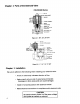
Chapter 2 Parts of the Solenoid Valve FSVlOO/200 Series PLUNGER ASSEMBLY PISTON SPRING SPLtTRING(TEFLON, PISTON BODY SEAT WASHER NUT Figure 2-1. 310”, l/2”, 314” NPT SOLENOID SPRING W AS HER --SOLENOID BONNET BOHET G PLUNGER ASSEMBLY PISTON SPRING SPLIT RING (TEFLON) -PISTON BODY Figure 2-2. I”, I%“, lYz”, 2” NPT Chapter 3 Installation Be sure to adhere to the following when installing your solenoid valve: Arrow on valve body indicates direction of flow.
Chapter 4 Troubleshooting Guide Problem Failure to open when solenoid engergized Failure to close when solenoid de-energized Leakage 1. Possible Cause Corrective Action Low voltage at solenoid (below 85% of rated voltage) Insure proper voltage at solenoid 2. Solenoid failure Check for excessive voltage at solenoid 3. Replace split rings Worn rings 4. Pressure drop less than 5 PSI Increase pressure differential to 5 PSI 5. Bonnet bent Install new bonnet 6.
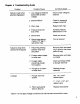
Chapter 5 Spare Parts List Coil with l/2” NPT Conduit outlet and 30” lead wires. Fits all valve sizes. Consult Factory for other voltages and coils with ground wire.
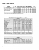
Chapter 6 Specifications FSVI OO/FSVZOO Series ri IT---- f’k II i-t I 0 0 F r-C--+ Figure 6-i. Figure 6-2. 1”, 1?4”, I%“, CL 2” 3/W ’, 112”, 8 314” FSVlOO: For fluids compatible with bronze, 430 F Stainless Steel, Ethylene Propylene, and Teflon pei P Size r otCv c Fa ounm Ther)aot c r of v FaC : ( et No dl be usedshou . owfl 318” 3. 2 l/2" 1 'I 314” 3. 3 5. 7 8. 9 l-114" l-112" 15 28 l-l/4" 7.25 3.29 l-112" 10.00 4.55 2" 39 son i r pa ma co 318" 2.00 0.91 Weight Lbs. Kgs.
Specifications (con?) Flow Capacity Charts 450 100 90 400 80 350 70 300 E 6o g5 E k 250 0 .E 20 0 175 30 15 0 E 125 100 .E 4 0 h. IA 30 20 ;i 10 5 0 5 IO 20 30 40 60 SO 100 125 150 :8 05 10 20 30 40 60 80 100 125 Pressure Drop Across the Valve in PSI Pressure Drop Across the Valve in PSI Figure 64. l”, I%“, I%“, 2” NPT Figure 6-3. 3/W ’, l/2”, 314” NPT * Valves require minimum 5 PSI pressure differentialfor reliable operation.
Notes
WARRANTY OMEGA warrants this unit to be free of defects in materials and workmanship and to give satisfactory service for a period of 13 months from date of purchase. OMEGA Warranty adds an additional one (1) month grace period to the normal one (1) year product warranty to cover handling and shipping time. This ensures that OMEGA ’s customers receive maximum coverage on each product. If the unit should malfunction, it must be returned to the factory for evaluation.
Where Do I Find Everything I Need for Process Measurement and Control? OMEGA...