TABLE OF CONTENTS General Information . . . . . . . . . . . . . . . . . . . . . . . . . . . . . . . . . . . . . . 2 Specifications . . . . . . . . . . . . . . . . . . . . . . . . . . . . . . . . . . . . . . . . . . . 2 Difference Specifications. . . . . . . . . . . . . . . . . . . . . . . . . . . . . . . . . . . 4 Features . . . . . . . . . . . . . . . . . . . . . . . . . . . . . . . . . . . . . . . . . . . . . . . 5 Manual Addenda. . . . . . . . . . . . . . . . . . . . . . . . . . . . . . . . . . .
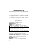
GENERAL INFORMATION This manual provides information on the use of three digital handheld thermometers. Functional features both common and unique to each model are described. All three models are microprocessor based, and provide accurate and reliable operation. They function with the most popular thermocouples; types K, J, and T. A variety of features in these projects enhance their versatility, while simplifying operation.
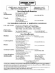
MAXIMUM COMMON MODE VOLTAGE: 42V peak to earth. POWER: 9 volt transistor battery (NEDA 1604). BATTERY LIFE, CONTINUOUS: 50 hrs typical, carbon-zinc; 100 hrs typical, alkaline; 200 hrs typical, lithium; 15 hrs typical, Ni-Cd (rechargeable). BATTERY INDICATOR: Display indicates BAT when less than 10% of life remains. DISPLAY: 5 digit LCD, 0.4" height. Polarity indication, and decimal point. Annunciators • Readout Parameter: T1, T2, T1-T2, SCAN • Record Parameter: MIN or MAX (when viewing recorded data).
DIFFERENCE SPECIFICATIONS MODEL HH-21: THERMOCOUPLE INPUTS: 1 DISPLAY: 5 digit LCD, 0.4" height. Polarity indication, and decimal point. Annunciators • Readout Scale: °F, °C • TC Type: K, J, T • Hold (when activated) KEYPAD: 5 momentary switches with tactile feedback select; • Power ON/OFF • TC type: K, J, T • Readout scale: °F/°C • Resolution: 0.1°/1° • Display Hold POWER OFF CONFIGURATION RETENTION: Instrument retains last selected; • TC type: K, J, T • Resolution: 0.
FEATURES • • • • • • • • • • • • • • Temperature trend indication (rising, falling, or stable) Full range resolution of 0.
SAFETY INFORMATION SAFETY SYMBOLS AND TERMS The symbol ! on the instrument denotes that the user should refer to the ▲ operating instructions. The WARNING used in this manual explains dangers that could result in personal injury or death. The CAUTION used in this manual explains hazards that could damage the instrument. SAFETY PRECAUTIONS WARNING These instruments are intended for use by qualified personnel trained in the safe operation of electronic testing equipment.
WARNING Do not substitute a metal part for the nylon screw in the rear case. Doing so will degrade electrical isolation of the case. WARNING The battery is accessible through a cover on the back of the instrument. To avoid electrical shock hazard, disconnect all temperature probes and sensors and turn the unit off before removing the cover. WARNING Never use this instrument or any probe or sensor inside a microwave oven. CAUTION Avoid making sharp bends in probe or sensor lead wires.
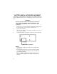
BATTERY INSTALLATION/REPLACEMENT A 9V battery is supplied with the instrument but not installed. Read the following installation instructions before attempting to install or remove the battery. WARNING Turn the unit off and disconnect any input connections before replacing the battery. Put the cover back into place on the battery compartment before resuming use of the instrument. 1. Remove the cover from the battery compartment by sliding it off in the direction of the arrow located on the battery cover.
MEMORY BACKUP During battery replacement, the contents of user-programmed memory (data, operating modes, etc.) can be saved. Prior to removing the old battery, turn off the instrument, and connect a Model 80010 battery charger. Then exchange batteries, and disconnect the battery charger. Do not leave the battery charger connected to instruments with non-rechargeable batteries. OPERATION WITH RECHARGEABLE BATTERY Model 80010 provides a 9-volt Ni-Cd battery and recharger suitable for use with the unit.
Display reads (1) No thermocouple or a damaged thermocouple is plugged into the selected input. NOTE: When viewing T1-T2, there must be a thermocouple plugged into both input jacks. Display reads momentarily. (1) This indicates that an invalid entry has been made. Review keystroke sequence, or consult manual for input instructions. Display reads during temperature measurement. (1) This indicates the temperature range has been exceeded for this thermocouple type.
2. R E C Record Annunciator A flashing record symbol adjacent to a corresponding input selection annunciator indicates that this channel is being recorded. A static record symbol indicates data has been recorded, but is not being updated. 3. Trend Indication Annunciators When the up-arrow is displayed, the reading is increasing. When the down-arrow is displayed, the reading is decreasing. When both arrows are displayed, the reading is stable.
10. HOLD Hold Annunciator This symbol will indicate that the instrument display is on hold. 11. SCAN Scan Annunciator This annunciator will be displayed when the instrument is sequentially viewing T1, T2 and T1-T2. 3. FUNCTION KEYS ON OFF The ON/OFF key turns the thermometer on or off. To turn the thermometer on, press the ON/OFF Key once. All the display annunciators and segments should turn on momentarily (see Figure 2) for visual checking.
0.1° 1° The DISPLAY RESOLUTION key selects whether the temperature readings will be displayed in high resolution (0.1°C or °F) or low resolution (1°C or °F). At initial power-up, the thermometer will read in high resolution. NOTE: • Key selection is retained during power off. K J T (or) SENSOR SELECT The THERMOCOUPLE TYPE SELECTION key selects which type of thermocouple the thermometer will be set up to use (Type K, J or T).
NOTE: The thermometer will display “OPEN” on any selected channel that does not have a thermocouple plugged in or if the thermocouple is open-circuited. CAUTION When using both thermocouple inputs, and a voltage differential exists between the two measurement points, at least one probe should be electrically insulated. NOTES: • T1 and T2 are not measured simultaneously. Therefore T1 and T2 readings can differ even when the temperatures are equal, if T1 and T2 are changing rapidly.
VIEW With the thermometer in either the T1, T2, or T1-T2 mode, corresponding MIN/MAX data can be viewed. To view MIN/MAX data, first select T1, T2, or T1-T2. Then press the VIEW key to read the MAX temperature. A second press of the VIEW key will display the MIN temperature. At the third press of the VIEW key, the display will go back to display the current temperature. To view a different input, select that input and repeat the procedure.
STOP CLR Recording in one or more of the three measurement modes T1, T2, and T1-T2 can be stopped with this key. Before pressing CLR this key, select the appropriate mode. When MIN/MAX data collection is stopped, the corresponding REC annunciator will stop flashing, but will remain on (to indicate that MIN/MAX data has been saved for viewing). Recording can be re-started anytime without loss of data with the REC key. See REC.
SERVICE INFORMATION WARNING All service information is intended for qualified electronic maintenance personnel only. 1. CALIBRATION PROCEDURE Test Equipment Required: 1. Thermocouple calibrator (Omega CL521, or equivalent). 2. Calibration cable for each thermocouple type handled by unit under test (U.U.T.): Type K Type J Type T Ambient Conditions: Units should be calibrated at an ambient temperature of 23°C ±1°C, with relative humidity less than 80%.
12. Wait for U.U.T. readout to stabilize, then press HOLD key once, and wait a few seconds. U.U.T. should read 32.0°F ±0.5°F, type J. 13. Set calibrator output to 1400°F, type J. 14. Wait for U.U.T. readout to stabilize, then press HOLD key once, and wait a few seconds. U.U.T. should read 1400.0°F ±1.0°F, type J. NOTE: On Model HH-22, go to step 21 to complete calibration. On Models HH-21 and HH-23, continue calibration at step 15. 15. Replace type J cable with Type T. 16.
Re-assemble the instrument by following the reverse of the above procedure. CAUTION Do not use excessive torque when re-installing the nylon machine-screw into the rear case. Excess torque will damage the part. WARNING Do not substitute a metal part for the nylon machinescrew. Doing so will degrade the electrical isolation of the instrument.
4.
5.
Schematic Designation* U9 U11 U12 U13 Y1 — — — — Description I.C., Schmitt Inv. I.C., LCD Controller I.C., EEPROM I.C., Microcomputer Resonator, Ceramic, 1MHz Keypad Connector, LCD Clip, Battery Header, Pin (3) * Numbers in parentheses refer to notes below: (1) Deleted from Model HH-21. (2) Matched pair.
6. SCHEMATIC DIAGRAMS 1.
2.
3.