HHTFO 1
TABLE OF CONTENTS 1 INTRODUCTION........................................................................................................................................................5 1.1 HHTFO PRODUCT SPECIFICATIONS ............................................................................................................................6 1.2 CALIBRATION........................................................................................................................................................
Warning Permanent damage may be done to the thermometer if the power supply connections are not done correctly. Only use the supplied 6VDC power supply module to operate the HHTFO; please note that this module will not charge any internal batteries. This product does not contain any user-serviceable parts. Opening this precision instrument will void its warranty and disturb its factory calibration. Always seek servicing from an authorized Omega Engineering service depot.
1 INTRODUCTION Congratulations on the purchase of your HHTFO Series thermometer product! Your new temperaturesensing instrument will soon allow you to take full advantage of the benefits inherent to fiber optic sensing technology. It offers accurate and reliable temperature measurements, combined with extraordinary insensitivity to EMI/RFI, high voltage insulation and disturbance free sensing due to the non-electrical nature of the sensor element used.
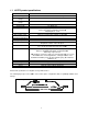
1.1 HHTFO product specifications Resolution Accuracy Calibrated Temperature Range Usable Temperature Range Number of channel Probe length Response time 0.1°C The Greater of 1°C or 1% of reading -40° to 200°C -80° to 250°C 1 1 to 300 meters Typically 0.
Coupling,, included with extension cable: FOBS-CAB-(*) Extension Cable Cable: Other options and configurations are also possible; contact Omega for more information. 1.2 Calibration Your HHTFO thermometer comes factory factory-calibrated. A re-calibration calibration is recommended every 12 months or whenever performance verification indicates that calibration is necessary; NIST traceable calibration certificates are available. All calibrations are performed at tthe e factory.
2 UNPACKING Before using your HHTFO thermometer, check the box content to be sure all items have been included. Your package should normally contain: • • • • • HHTFO signal conditioner unit Power supply module (universal input: 100-240VAC, 50/60Hz; output: 6VDC). Note: this is not a battery charger. Short extension cord and mating sleeve (should be used to minimize damages to the connector at the HHTFO interface) User manual (this manual) Calibration Certificate.
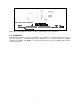
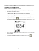
3 QUICK INTRODUCTION The best way to familiarize you with your new HHTFO thermometer is, of course, to use it! This chapter shows you how to prepare your unit and do some initial measurements. The detailed instructions are given in the next Chapter. Your new HHTFO comes calibrated and ready to use. If the unit has not been used already, install fresh AA alkaline or rechargeable batteries. This figure shows the main view of the HHTFO, along with the top and bottom views.
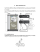
Note: A small battery inside the HHTFO keeps the time and date running even when the main batteries are not installed or when the AC power module is not used. This small battery has a nominal lifetime of 10 years. 3.2 Making your first measurements To make your first temperature measurement, do as follows: • Remove the dust cap on the e optical connector of the HHTFO (located on the top of the HHTFO). HHTFO • Remove the dust cap on the probe connector.
4 HHTFO THERMOMETER HARDWARE REFERENCE ENCE 4.1 Display description The display is organized in 3 logical regions: • The top portion gives general information to the user about the unit current status, such as battery condition, RS232 port connection status, time and date, presence / absence of a SD memory card, and so forth. be e displayed here. here • The middle portion displays the temperature value.
The Up and Down keys can be used to: • When inside a menu, to select a parameter • When a parameter is highlighted, to change its value • The Up key can be used to snap the present temperature value to the logging file The Left and Right arrows can be used to: • When at the first menu level, can be used to select one of the four main menu items • The Left arrow can be used to move up between menu levels 4.
Warning The flash card must be formatted before use. Furthermore, it is important to format it in FAT or FAT16 (not FAT32). Supported card size is limited to 1Gbyte (larger formats are not supported by FAT16). You can format your flash cards on a PC, if you want; however, make sure you format it in FAT16. The HHTFO includes a format command, where FAT16 is always used. The HHTFO is designed so it can only write to SD flash cards.
Take note that this format function will only perform a “quick format” procedure; if you want to do a full format, please use your PC to perform a format operation. Furthermore, you will not be able to format a flash card that is not already formatted in FAT16 (use a PC computer to format a card that would be in FAT32). 4.5.3 The Enable sub-menu This sub-menu allows you to engage or disengage the logging feature. This parameter must be ON to be able to do logging.
The lock feature on your SD card is engaged. You need to unlock it before using the card. The HHTFO is running from the internal batteries. Icon indicates the approximate amount of charge remaining. When almost fully empty, the message “LOW BATTERY” is also displayed, for about 5 to 15 minutes, before auto-shutting off without further warning.
5 USING TEMPERATURE PROBES 5.1 Caution Each time you connect a temperature probe to the unit, the probe optical connector should be cleaned beforehand. Otherwise, particles of grease or dirt may obstruct the device internal connector and affect the measurements by completely blocking the signal or by generating too much attenuation when using a long fiber length. Never use a cloth other than the type recommended for fiber optic cleaning. Dampening the cloth with pure isopropyl alcohol ensures good cleaning.
5.3 Warning The T1 probe is quite fragile and it must be handled carefully. Please note that any probe damages are not covered by the standard warranty. The probe tip is made of silicone rubber. Although silicone is resistant to a large number of chemical aggressors, strong acids or alkali may damage it, especially at high temperature and/or if used for extended periods of time. Warning: Strong solvents and fuel oils can cause problems for silicone rubber.
6 SERIAL COMMUNICATION DESCRIPTION You can communicate with your thermometer via the standard RS-232 link. A description of the cable requirements is given above, under front panel item # 3. RS-232 functions (or commands) can be accessed with a simple terminal, with the FOB100-SOFT software package or simply with a computer and communication software (such as Windows Hyper Terminal). Your software should be set at 9600 Baud, 1 Stop-Bit and No-Parity. 6.
HHTFO101 Description b Return enclosure temperature f[j] Set point adjustment to [j] h Help menu (this screen) i Get factory and status information q Scanning rate (q+ for fast/quick, q- for slow) t Get Temperature reading channel ta[i] Auto temperature output to serial port (+ to enable, - to disable) u[i] Unit (c = Celcius, f = Fahrenheit) y Probe power o o 6.3 Detailed description of RS-232 commands All commands must be terminated by a carriage return character ( E ).
“i” Returns general information regarding the instrument, as well as some parameters that have been programmed previously in the thermometer (either by RS-232 commands or via the keypad): Ex: Model: HHTFO101 Option: NB Channel: 1 Mode: Continuous Scanning Mode Scanning rate: Fast Serial: HHTFO111A Internal Software: V1.21 Last Factory Calibration*: 05/02/04 (YY/MM/DD) o Unit C Keyboard Status: Unlock Channel Zero Span Enabled Temperature offset* 1 xxx.x xxx.x Yes/No ±xxxx.
6.4 Typical temperature reading sequence Once all parameters have been set, the following sequence should normally be followed to extract temperature information from your FOB100 thermometer. 2 procedures can be used for this purpose. The first method consists in using the “ta” command (preferred), while the second sequence would be: a) The host computer should send the “t” (or “t[i]”) command, followed by a E character.
7 ERROR CODES The following error messages are displayed under certain error conditions: RS-232 Err2 Display Err2 Analog Out “- - . -” Err5 Err6 “- - - - -” Hi-Lo, 0.5 Hz* Description Internal memory checksum error. Memory corruption. Contact Omega. Temperature out of maximum instrument limits or no signal Argument out of range Unrecognized command *: The exact analog output behavior is a function of the command “o”; see previous Chapter.
8 FOB100-SOFT SOFTWARE PACKAGE The FOB100-SOFT software package option allows using your thermometer system in a highly flexible manner. The built-in functions allow for temperature displaying and data logging, as well as exporting to a variety of standard spreadsheet packages. This software supports both the FOB100 series and HHTFO101 fiber optic thermometers. 8.
You should normally see a window similar to this: In this example, we see that FOB100-SOFT has detected 2 thermometers: a FOB104 and a HHTFO instruments. FOB100-SOFT is now properly installed and ready to use! 8.2.1 Working with the Configuration Window FOB100-SOFT starts with the “Acquisition” window active, as shown in the figure above.
For each instrument, this configuration window gives some information about this particular information and allows you to set some parameters. The top portion of the window gives information about the specifics of the thermometer, such as: • COM Port number • Serial Number • Calibration date. Description of the parameters that can be set: o o • Unit: You can select C or F. • Scan Rate: Fast (recommended for most application) or Slow.
Warning: Doing a temperature offset adjustment on a channel will alter its reading. In effect, it alters the thermometer own calibration. It must be used with care! To perform an offset adjustment, follow these instructions: 1- Click the “Offset Adjust” button ( ) that is just next to the channel number you want to calibrate.
• To start acquiring data, click the “START” button. Conversely, to stop the acquisition, click the “STOP” button. When subsequently trying to opening the *.tem file, it is possible that you may get the following message: Select “Select the program from a list”, and click OK. In the next window, you should instruct Windows to always open this type of file with Microsoft Excel. If you get the following message, you should select “Read Only”.
When logging temperatures for a very long time, one needs to note that a standard Excel sheet is limited to 65535 lines. If this limit is reached (65000 lines), the logging process will close the current data-logging file, and will open a new one, with the same name but with “_1” appended to the file name, and so on (“_2” …), until the application is stopped or your disk becomes full. 8.3.2 Viewing temperature data Temperature values can be displayed on your computer screen in a number of ways.
Adjust the “Refresh Rate” (minimum is 0.2 sec) and Min / Max to suit your viewing needs. Note that the setting of curve colors and other parameters must be done in the “System Configuration” window pane. Up to 64 trends can be displayed. 8.3.2.2 Displaying analog thermometers Click the “Thermo” button; the following window will appear. All thermometers share the same Min / Max reading setting. Refresh rate is fixed at 1.0 sec.
All dials share the same Min / Max reading setting. Refresh rate is always 1.0 sec. The size of this window will adapt to the number of displayed channels. Up to 16 dials can be shown; if you want to display more than 16 channels, only the first 16 detected channels will be shown (note that any channel that has its “Chart” checkbox unchecked, in the main window, will not be shown).
Before sending commands and receiving information from a specific module, it is necessary to select the instrument you want to interrogate. Please note that only ONE instrument can be selected at a time; if the same command is to be sent to all thermometers, then, it is necessary to repeat the command for each individual module.
8.5.1.3 Advance serial port setting This command allows the user to force the exclusion of one or more COM ports from being scanned when clicking the “Refresh” button. This may be useful when one finds that the automatic COM port refresh feature of FOB100-SOFT is interfering with equipment that are using defined COM ports. You can check all ports that you want to exclude from the automatic scanning process. This window looks like this: 8.5.1.4 Quit Select Quit from the File menu to exit FOB100-SOFT.